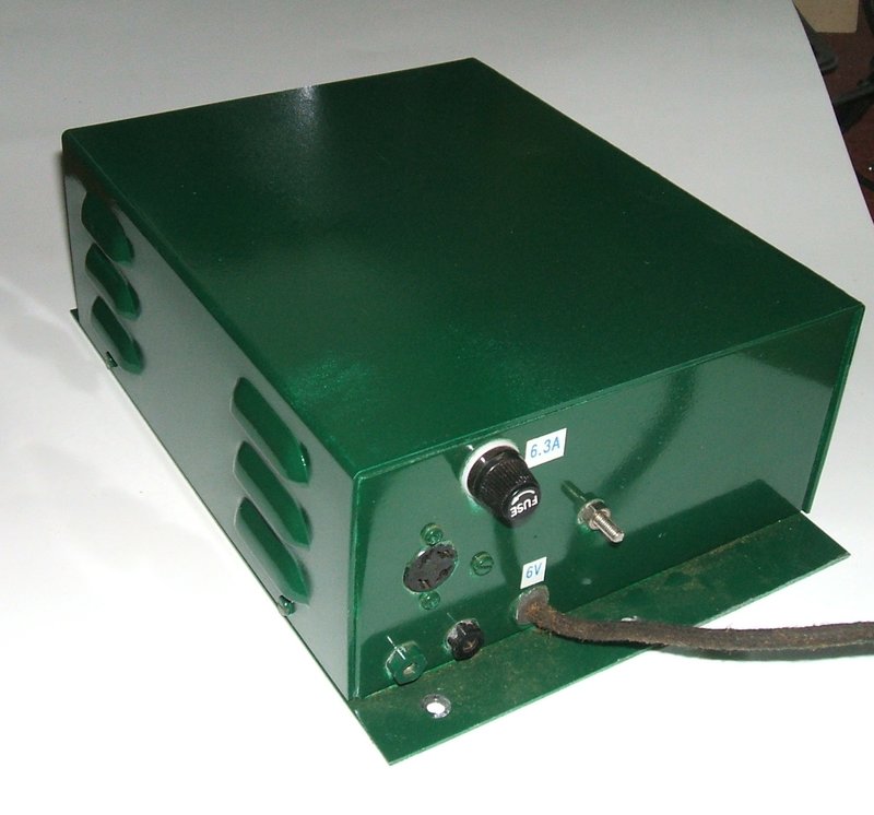
The receiver is used with a remote control unit and external speaker. The four pin socket to connect to the remote control can be seen here. Below are the speaker connections.
The receiver is used with a remote control unit and external speaker.
The four pin socket to connect to the remote control can be seen here.
Below are the speaker connections.
This is not the first radio to be installed
in my Model T. The original design was installed in the car just prior
to the Parkes trip, Easter 2004, and worked faultlessly. It was something
new and untried to have a radio in the Model T, so there was a lot to learn.
My original set was a hybrid design using a TDA7000 for the receiver and
valves for the audio. FM only reception was chosen because of the RFI caused
by the Model T ignition system. By mid 2006, I had enough experience with
this radio to make a few changes. For one thing, I was never really happy
about the solid state method of reception. While the TDA7000 works very
well, it was just out of place in a Model T. The new set would be all valve.
See the new set operating here https://www.youtube.com/watch?v=L6_U9xOBTns
The physical aspects of the set are based
on typical 1930's designs where all the circuitry is mounted in a box mounted
in a remote location, usually under a seat or on the firewall. The controls
are mounted on the dash or steering column, and operate the tuning condenser
and volume control in the receiver box via Bowden cables.
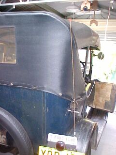
In the case of a 1926 Model T Ford, the
petrol tank occupies most of the behind dash space, so it is not practical
to mount the receiver there. The best location is therefore under the front
seat. With varicap diodes taking place of the tuning condenser, it is possible
in the modern day to eliminate the Bowden cables, and simply connect the
receiver to the remote control with ordinary wires. There is enough room
under the dash for a small remote control, or alternatively, the steering
column could be used. The remaining challenge is somewhere to put the speaker.
For convenience, and unobtrusiveness, I mounted it on the steering column
under the dash.
Limitations of a radio in the Model
T
First problem and one that can't really
be solved is the noise that one is subjected to in an open touring car.
The only way to deal with this is the brute force method; try and make
the radio louder. One thing that was immediately evident is that it is
a waste of time to achieve high fidelity sound. With all the noise present,
the lower level components in the audio signal aren't really heard anyway.
The other thing noted with the sound was that good bass response was pointless.
The low frequency components are masked by the rumbling of the engine.
The ignition system of a Model T is famed
for the RF interference it causes, and initially it was thought there might
be problems. This didn't turn out to be the case at all. Firstly this is
because the radio was VHF FM, and again what interference finds its way
into the radio is masked by the road and engine noise. So, that's a non
issue, unless you want Medium Wave AM. Even then from the experiments I
did try back in 2004, it seems that it might not be a lost cause. Bypass
condensers around the supply for the ignition coils might just improve
things.
The electrical system is a limiting factor
for the design of the radio. With only 5A available without discharging
the battery, the current consumption needs to be thought out carefully
and minimised. Unfortunately, this means being stuck with a single ended
output stage providing about 2.5W into the speaker. As much as I'd like
a push pull output or my 6CM5 amplifier (3.8W) the extra current required
is too much. It is true I could set the generator charge to a higher rate.
This would however overcharge the battery when the radio wasn't on, and
also the generator wear would be greater. The Model T uses a 3rd brush
type of generator which functions as a constant current source. There is
no voltage regulator. Charging current is set by the position of the 3rd
brush on the commutator.
The other limitations concerning radio
installation is where to put the radio. The under seat approach with a
remote control under the dash works very well. That aspect of the original
design would stay. The speaker position behind the steering column under
the dash is acoustically poor but physically convenient and out of sight.
A smaller speaker under the dash pointed at the occupants would probably
be better.
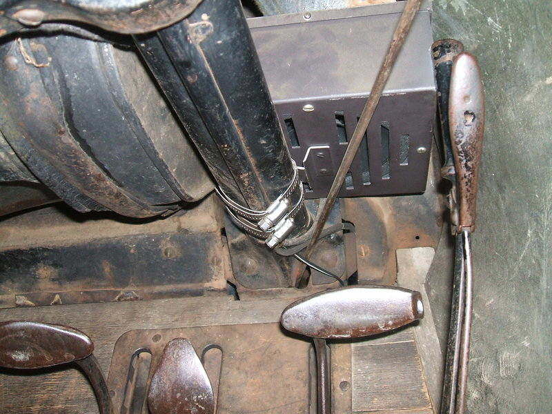
The speaker box is secured above the steering column with hose clamps.
This eliminates holes being drilled. The handbrake fully forward almost
touches the box.
The New Design
One of the things I wanted in the new
radio was a smaller remote control unit. Previously, this contained the
TDA7000 receiving circuit and a slide rule dial, and did look obvious,
much like a modern car radio. It was decided to move the receiver into
the main unit which would simplify, and miniaturise the remote control
unit. Additionally, this would tidy up the cabling, with the RG59 aerial
cable only having to go so far as the main unit under the seat, instead
of all the way up to the dash. Acquiring a small rectangular speaker that
could handle 2.5W with tolerable quality wasn't easy, so for now the idea
of speaker in the remote unit was overlooked and the existing speaker used.
Electrically, the new receiver wasn't going
to be much different to the previous, as far as audio and power supply
was concerned. However, the receiving circuit was now going to be my trusty
12AT7 super-regenerative receiver. No matter how well it works, the TDA7000
is a solid state IC and just seemed out of place in an 80 year old car.
The annoying thing I did find with the TDA7000 is how sharp the tuning
is. Even with the gearing down of the dial it was still critical and an
awful sound issued forth if the receiver was slightly off tune. With the
super-regenerative approach, the sound merely becomes more distorted as
tuning varies from the optimum setting. Using a super-regenerative detector
makes this an AM receiver (FM to AM conversion occurs by tuning the aerial
coil slightly off frequency; i.e., slope detection). This might be assumed
to be a problem so close to those four unsupressed ignition coils, but
not so. Firstly, there's less RFI at VHF, and also a super-regenerative
detector has inherent noise suppression. How? It's because detection actually
takes place only during the short periods when the detector builds up to
oscillation. The rest of the time anything received is ignored. It actually
acts as a sampling type of receiver, with the short samples fed into a
low pass filter to recreate the original modulation signal.
Obviously, with the new radio, tuning
would have to be done by varicap diodes controlled by a pot at the remote
control.
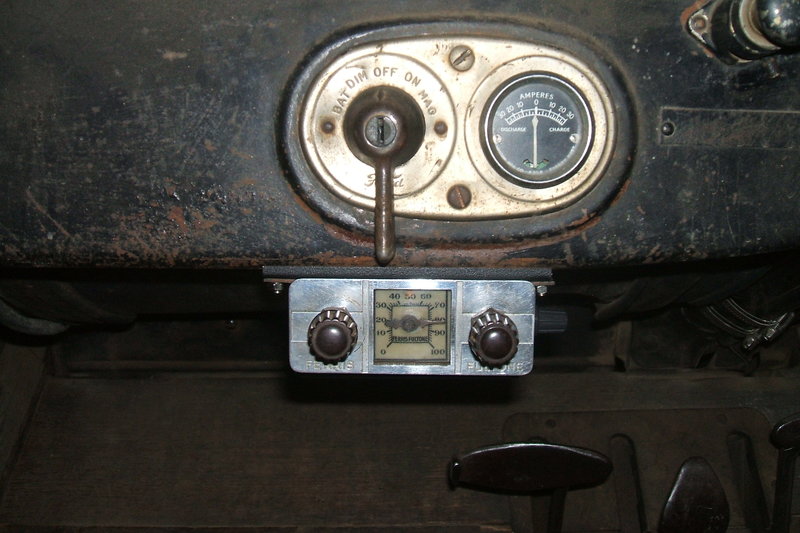
The remote control clamps to the lip under the dash avoiding having
to make any holes. Power / volume is on left. Tuning is on right. On the
extreme right side can just be seen the regeneration control. It seldom
needs adjustment.
As far as the audio section is concerned, there would be no negative feedback. The improvement in sound quality is totally wasted in this application. Additionally, it detracts from useful gain which is important when trying to minimise the amount of valves used. Furthermore, the frequency response would be concentrated with the mid and high range components. It's better to concentrate the power in the frequency range that can be heard above the engine noise.
The New Radio
Construction of the main unit chassis
and enclosure was virtually a copy of the original, as it was easy to construct
and served the purpose well. Layout was much the same too, but the height
of the cabinet was reduced as the original was a tight fit under the seat
cross member.
I also wanted the new radio to use the
existing wiring harness between the main unit, remote control, and speaker.
This meant six wires were available.
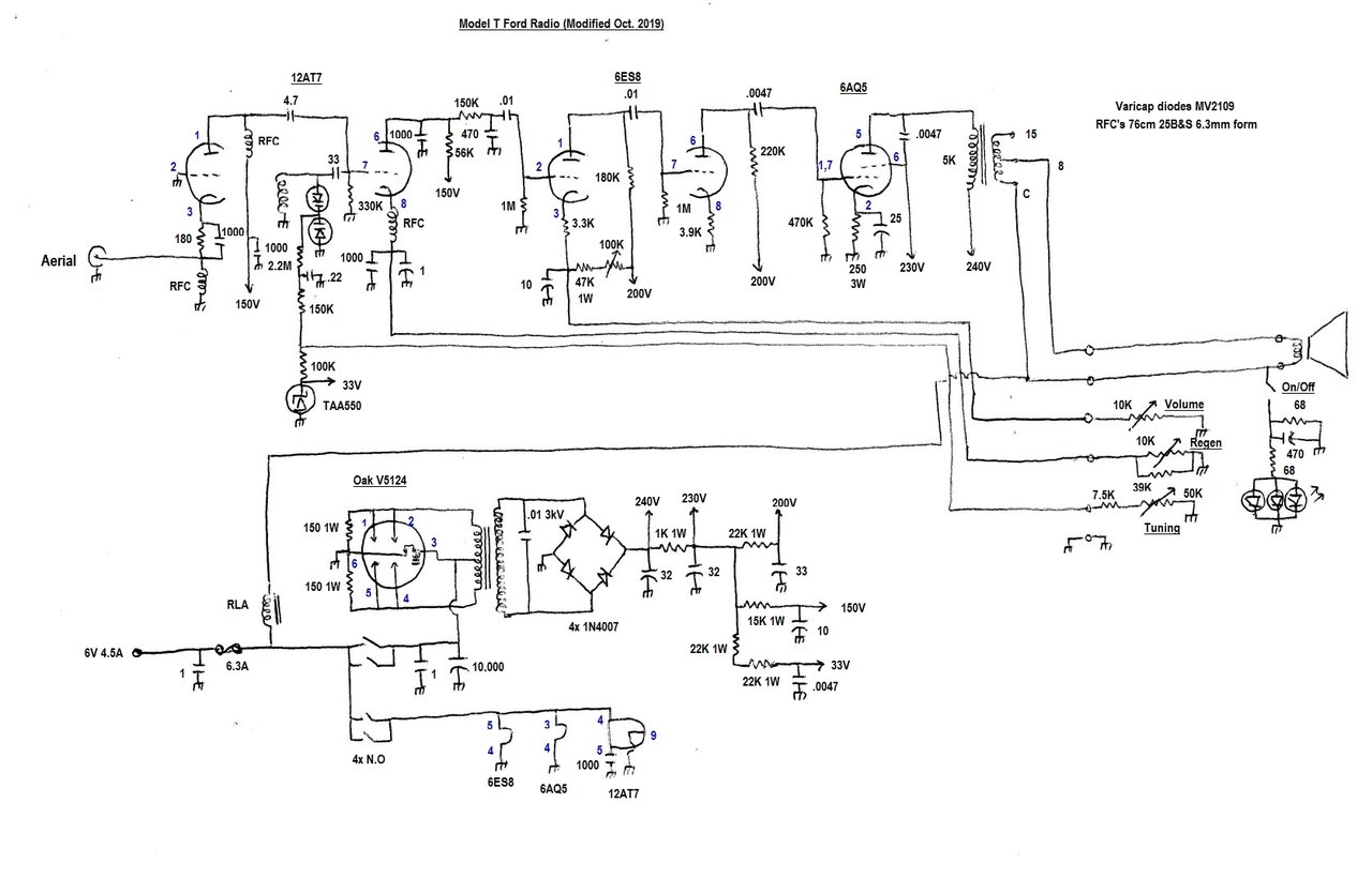
Let's now analyse the circuit:
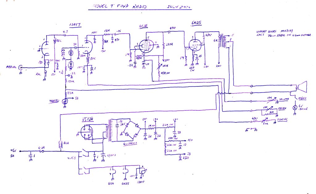
The circuit of the Model T Ford radio receiver. The remote
control unit circuit shown is for the original; it was altered later. Note
the freedom from unnecessary parts...much like the car itself.
Super-Regenerative Detector.
This 12AT7 circuit has been discussed
elsewhere on this site so I won't repeat it all, except to mention a few
slight differences. With the 15uH RFC's I'd been using up to now,
no longer available, I had to make them. They're of the same design as
used in the 6C4 receivers. 76cm of 25B&S wound over a 6.3mm plastic
former. While other 15uH chokes are available, they are of the axial type
and do not work in this circuit. The home made chokes actually are better
than the original 15uH ones and will allow the use of a 12AU7 instead of
a 12AT7. Regeneration control is by means of a cathode rheostat, but in
this receiver I've simplified the arrangement by not having any bleed current.
An advantage of this also is the current consumption is reduced. Remember,
the current consumption of anything drawing off the B+ is multiplied by
about 40 times as far as the six volt supply is concerned. The other reason
for doing this was to eliminate another wire in the cable up to the remote
unit. To do this means a higher value of pot than used previously. A 10K
pot turned out to be a good choice, shunted by a 39K to restrict the range.
Furthermore, the cathode rheostat, with no bleed current, actually provides
a degree of automatic regeneration control. The regeneration control, once
set, does not normally need further adjustment when tuning across the band.
The receiver sub chassis undergoing testing and optimisation of
the circuit.
One interesting thing that had me confused
for a while was poor oscillation, especially at the 88Mc/s end of the band.
Nothing made sense. I'd isolated the RF amp in case that was loading the
detector. The circuit was checked. The chokes were identical to that in
the 6C4 receiver which has no problem in this regard. Then something occurred
to me...what if there was magnetic coupling between the cathode choke and
the
aerial coil and causing negative feedback. Then it wouldn't oscillate!
But why in this receiver?
What a trap this was...I looked at the
direction of the windings of both coils...took the choke out and reversed
it. What a difference! Good solid oscillation all over the band at last.
Tuning by DC
Short of using bowden cables linked to
a variable condenser, the tuning control had to use a potentiometer varying
a DC voltage. The obvious choice is to use varicap diodes for tuning and
here I ran into problems. As expected the Q was less than a variable condenser
and this prevented a 12AU7 being used. At first I tried a pair of BB105
diodes but couldn't get sufficient capacitance. Strange, as I'd used these
in my 12V pulse counting receiver with no problems. I then tried MV2109's
and at last was able to get the correct tuning range with a maximum reverse
voltage of about nine. The MV2109's also had much better Q as made evident
by stronger oscillation. One of the other worries about using varicaps
is the tuning voltage supply drift. Rather than use a zener diode, the
correct way is to use a special tuning voltage stabiliser IC, such as the
TAA550 or ZTK33. While these appear electrically as a zener diode, they
are constructed quite differently, and specifically designed to have good
temperature stability. The regulated voltage is approximately 33V. Again,
to simplify the wiring between units, the tuning pot is wired as a rheostat
and shunts the tuning voltage to earth. The combination of the 82K, 4.7K
and a 50K tuning pot provides the correct 88-108Mc/s coverage. The .22uF
simply shunts any noise to earth and any remaining RF at the supply end
of the 2.2M. Or so I thought. With the receiver up and running, I noticed
the volume setting had an effect on the tuning. Even with the volume control
wire disconnected at the receiver the effect was still there. Something
capacitive must be happening. The only other wire going into the wiring
harness was the tuning wire.
Well, despite the .22uF there must have
been RF flowing where it shouldn't. The 150K decoupler fixed that and now
the receiver was so much more docile and behaved just like it should.
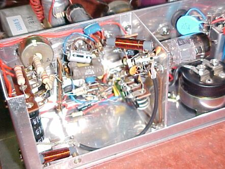
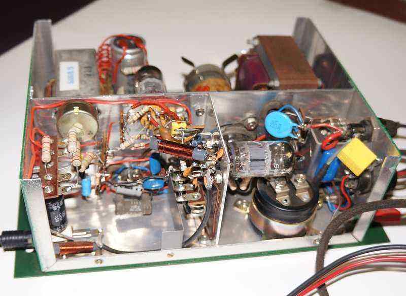
Close up of where most of the action is. The minimum volume preset
is upper left, with the power supply filtering components in front of it.
Two of the RFC's are visible along with the aerial coil towards the bottom
of the 12AT7 sub chassis. To the right is the 10,000uF electrolytic for
filtering the incoming 6v supply. The .01uF 3KV buffer condenser is clearly
visible behind the 12AT7.
The DC volume control.
This is a novel piece of circuitry I developed
for the original radio. Apart from requiring only one wire to control the
volume rather than three, any noise picked up on the wire would be shunted
to earth by a condenser, as we only want the DC voltage.
As before, I used a 6CS6, known in Europe
as EH90. It's a pentagrid valve similar to a 6BE6, and was popular for
TV use in Australia as a noise gated sync separator. By feeding a signal
into one of the control grids, the other control grid voltage will affect
the gain. In my circuit, an even better range of control is obtained
by varying the DC on both control grids. That is simply done by earthing
both grids (DC wise) and varying the cathode voltage. In case you are wondering
why I didn't use a 6BA6 or other remote cutoff pentode, it's because of
the range of control voltage required. The 6BA6 required about 30V to cut
it off; the 6CS6 about 16V. Why does this matter? Again, a rheostat wired
pot is used to control the volume. With the pot at minimum resistance,
the bleed current is fairly high in order to obtain 30V at max resistance;
compared to when only 16V is required. There's a preset 100K pot in the
main unit to set the bleed current, and therefore the minimum volume, when
the volume control is set to it's maximum 10K resistance.
The DC volume control works extremely
well. From a user point of view it is indistinguishable from the conventional
audio voltage divider type of circuit. Gain from this section also brings
up the detected audio level to drive the 6AQ5 output.
The power amplifier
This is a stock standard 6AQ5 output stage.
I kept to the 6AQ5 as it provides the most power output for the least heater
current, and I have a good collection of them. As mentioned before, no
feedback is applied. The input signal has the bass frequencies attenuated
by the .0047uF grid coupler. Realistically, the output power into the speaker
is about 2.5W which is typical for a cathode biassed 6AQ5 running off about
250V B+. Plate voltage is effectively lessened by the drop across the speaker
transformer and cathode resistor. One thing I was determined to do is use
a proper valve output transformer. Previously I'd used a 100V line transformer
which did a good job, but with not an exact impedance match, and interleaved
laminations, wasn't the most efficient thing to do. I decided on a chunky
Rola B23 transformer. The core looks like it could easily handle 10W. The
impedance ratio is 5000 to 15 ohms which is just right for a 6AQ5. It wasn't
right for the 8 ohm speaker however, so I simply unwound the secondary
and brought a tap out. I rewound the rest of the secondary back on so I'd
still have the option of using a 15 (or 16) ohm speaker in the future.
The power supply
No prizes for guessing I'd use a vibrator
power supply; after all that's part of the charm of a valve car radio.
I had hoped to use a synchronous vibrator in the normal self rectifying
circuit, but the only transformer I had for this purpose seemed to have
a strange characteristic or some sort of fault. It was a new old stock
transformer made by Astor. It was labelled as 6V which was what I needed,
and indeed when I built the radio up and used it, there was the 250V at
50mA I wanted. Alas, before the radio warmed up and was drawing B+ current,
the no load voltage was horrendously high. The secondary vibrator contacts
were arcing over, not only between themselves, but through the mica washers
in the base of the vibrator. The .01uF buffer condenser rated at 3KV eventually
went up in smoke! This transformer was obviously a lost cause, so the next
in turn to try was a mains transformer, with a secondary I'd rewound to
give a suitable turns ratio for 6 to 250V vibrator use. It was a Telefunken
transformer that looked like it was from the 1960's. I have no idea what
it was out of, with a secondary voltage of about 7 and tapping of about
3.8V. Conveniently, this was rather close to what I needed, and the core
size and wire gauge looked perfect for what I wanted. As it was, despite
the uneven "centre tap" I powered up the transformer from a vibrator and
it worked quite well. However, this winding now functioning as the primary
was contributing to DC through the core with the asymmetrical tapping.
It would have been tolerable if necessary, but I did the right thing and
rewound it, bringing up the efficiency by a worthwhile amount.
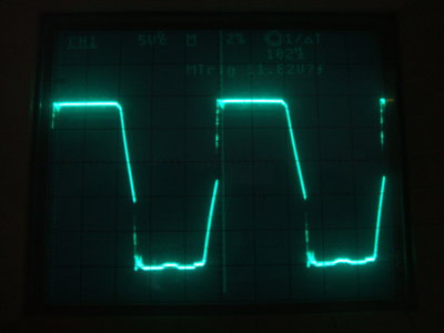
Vibrator waveform is text book quality.
I like the idea of a self rectifying synchronous
vibrator, but alas with a single 250V winding it wasn't going to happen
in this radio. So, in with the 1N4007's. Not quite keeping in with the
theme but they work well, and are reliable with the high unloaded voltages
from a vibrator supply. Schemes involving valve rectifiers were ruled out
given the extra current consumption. I retained the synchronous vibrator,
and simply paralleled the primary and secondary contacts to convert it
to non synchronous operation. The vibrator is an Oak V5124.
On the six volt side of things, the heaters
and inverter are switched by a relay. This is done to eliminate the stress
on the power switch contacts. It also eliminates another wire to the remote
control unit, as the radio is turned on by earthing only one wire. Incidentally,
to keep down on the wiring between units, the switch wire is common with
one of the speaker wires.
The incandescent dial lamp of the original
control head was actually in series with the relay coil. This eliminates
the extra current consumption that would come from simply wiring the dial
lamp across the 6V supply.
It may be thought that a 6V relay would
not function with so much voltage dropped across the lamp (about 3V). It
works perfectly, making use of two well known properties about both components.
Firstly, an incandescent lamp has a low filament resistance when cold;
i.e., soon as the radio is switched on. Secondly, the holding current required
for a relay coil is a fraction of that required to pull it in. So when
turned on, the relay receives pretty much full current. The lamp warms
up in less than a second by which time the relay has pulled in.
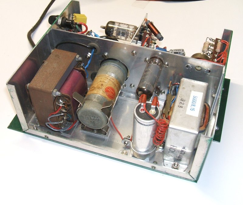
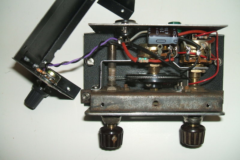
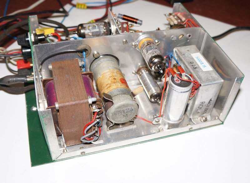
The finished radio. The 6AQ5 is between the vibrator and speaker
transformer, with the 6CS6 beneath it. Note the size of the speaker
transformer to right of the 6AQ5.
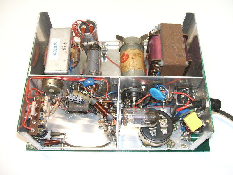
Wiring and components can be seen from this side. At the left is
the super-regenerative detector and audio circuitry. At the right is the
power supply.
Much to my delight, the vibrator interference
was easy to eliminate. First thing was to add the 10,000uF condenser right
at the vibrator socket. Car radio manufacturers would have loved such high
values back in the 1950's! This eliminated most of it, but being a perfectionist
I tried connecting a 1uF polyester against parts of the 6V supply and found
another chunk of noise gone at the relay contacts. The last of it disappeared
with another 1uF (the yellow thing in the pic above) from the fuseholder
to earth. Elimination of vibrator interference is really an art. You can't
tell the steps needed until the radio has actually been built.
After all this, the radio was putting
on a really impressive performance, working as well as a mains powered
unit. The case was etch primed and painted in green enamel. Installed in
the car with the existing aerial there was no doubt about the sensitivity,
with 2ST from the southern highlands coming in better than it does with
most receivers.
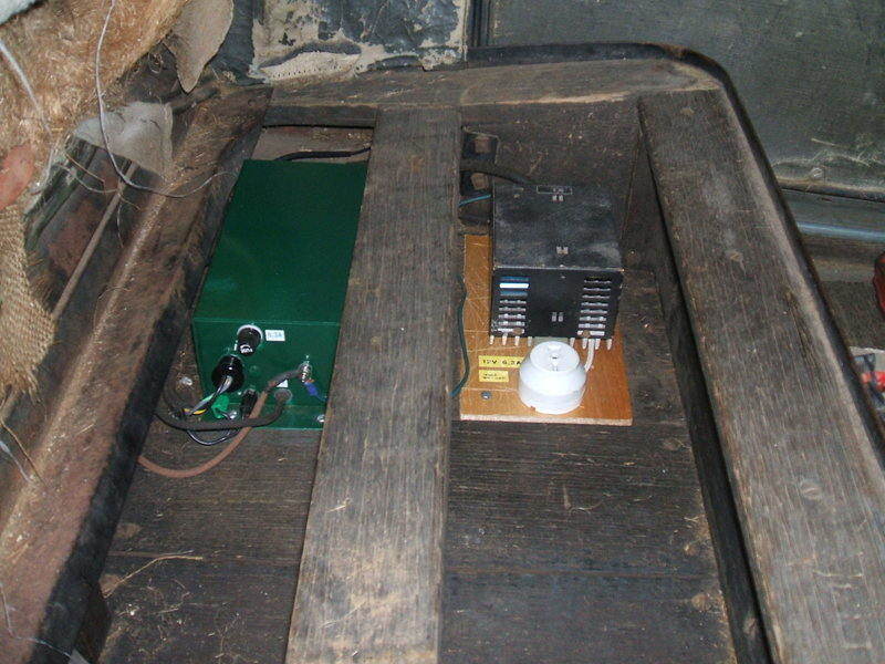
The radio fits under the front seat. The black box to the right
is a 6 to 12v converter used to power appliances such as a car fridge and
air compressor.
Remote Control Unit.
Originally as the radio was built in 2006,
I used a 10 turn pot for tuning. The intention was to eventually build
a remote control with a proper vintage looking dial.
Original control unit while functional did not look antiquated enough.
Also, the dial was hard to read while driving.
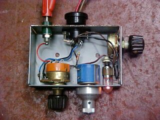
Inside the original remote control unit. From left to right is the
on/off volume control, ten turn tuning pot, dial lamp, and to the
side is the regeneration control.
The original worked well, but always looked
out of place. In 2019, a control unit from a Ferris model 56 turned up
in a box of junk at the HRSA. Realistically, a complete 56 isn't likely
to turn up (as much as I'd like one) so it was decided to rebuild the control
unit for the Model T radio.
As the 56 was produced from 1938 to 1939,
the dial and surround has an art deco appearance, and looks the part for
the Model T. As with all such units, the control head operated the radio
via bowden cables. To use it with the Model T radio would entail removing
everything but the actual dial, and fitting potentiometers instead. Also,
the existing 6.3V dial lamp would not be suitable.
The rebuild was extensive, with a lot
of intricate metal work and brackets to be made up.
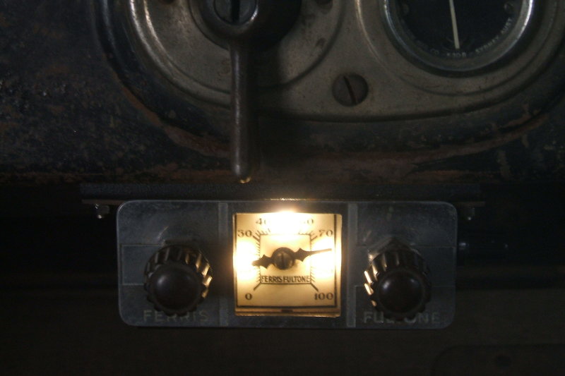
Inside the rebuilt Ferris control unit.
The tuning potentiometer had to have the shaft drilled and tapped to take the dial pointer. The existing dial drum was not suitable, so a plastic one had to be used. It is of larger diameter, which meant the enclosure for the whole thing would no longer fit. A larger enclosure was made up. A bracket had to be made to support the volume and tuning pots. The existing dial pulley was used. The regeneration pot was mounted at the side of the enclosure.
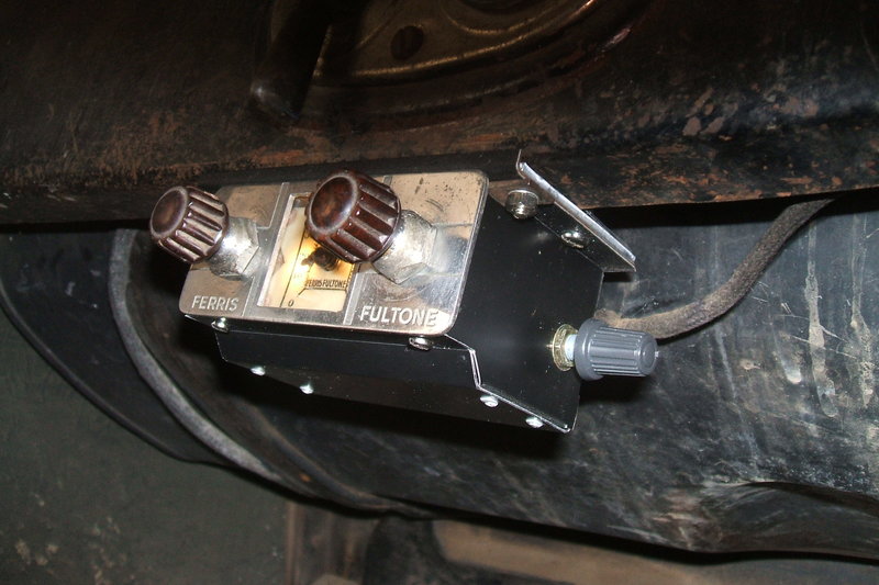
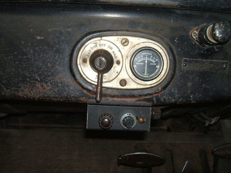
Control unit is clamped to the lip under the dash without drilling
any holes.
As far as the tuning and volume controls were concerned, these were the same as the original control unit, except that the resistor in series with the tuning pot needed to be increased from 4.7K to 7.5K. This was because there was too much below band coverage.
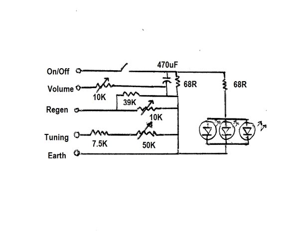
Circuit of the new remote control. Speaker connections not shown,
but one is common with the on/off control as previously.
The regeneration control also remained the same, with a 39K resistor to reduce the amount of dead spot with the 10K pot. The dial lamps were the next challenge. Now the dial actually had to be illuminated. In the previous remote control, the dial lamp was merely a power on indicator, which glowed at less than half brilliance. Because of the dial lamp having to be in series with the relay coil, options are limited. With only about 50mA available, it would be difficult to use an incandescent lamp and light the whole dial. Therefore, it was decided to use LED's.
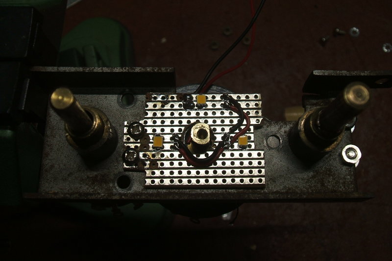
Three SMD LED's provide dial illumination.
Three warm white surface mount LED's were obtained from a burnt out 240V light bulb. They were mounted on a piece of Verobard behind the dial. This worked exceptionally well, and only a few mA were needed to give bright illumination. Next was to modify the on/off circuit to operate with the LED's. With no more incandescent bulb providing an initial low resistance in series with the relay, a 470uF capacitor was used instead. It was found for reliable relay operation, that the maximum resistance in series along with the 470uF, was 68R. This allowed about 3.6V for the LED's which was perfect. Next was the LED series resistor. While it's not the best way to do things, the three LED's were connected in parallel, and the current sharing seemed even enough, with equal brightness. In series with the LED's the current limiting resistor was 68R to give a sufficient brightness to see that the radio is switched on in daylight. In the dark the brightness is perhaps more than required, and thoughts are to use an LDR to automatically reduce brightness.
Dial lamps appear brighter than they are due to the camera.
The final part of construction was the
dial "glass". There was none present when I got the control, and it would
have been a piece of celluloid. I had ideas of using a piece of Lexan,
but the thinnest piece I had was still too thick for the panel nuts to
grip the control shaft surrounds.
I simply used a piece of plastic cut from
some packaging. It has perfect transparency, is thin enough, yet stiff
enough to protect the dial. In fact, the kind of plastic used is very similar
to the original celluloid.
The Aerial.
Aerial is a 75cm brass rod.
The aerial is a 75cm brass rod attached
to a PL-259 plug. It is supported in the plug body, and insulated from
it by a piece of plastic rod turned down to suit. This bites into the thread
of the plug body making a very secure attachment.
The PL-259 plug is then attached
to a panel mount joiner, which is mounted on a Marvi-Plate bracket secured
to the number plate mounting. From the other end of the joiner, the RG-59
coaxial cable connects via another PL-259 plug. The coax was shrouded in
black shoe lace to give it the vintage appearance.
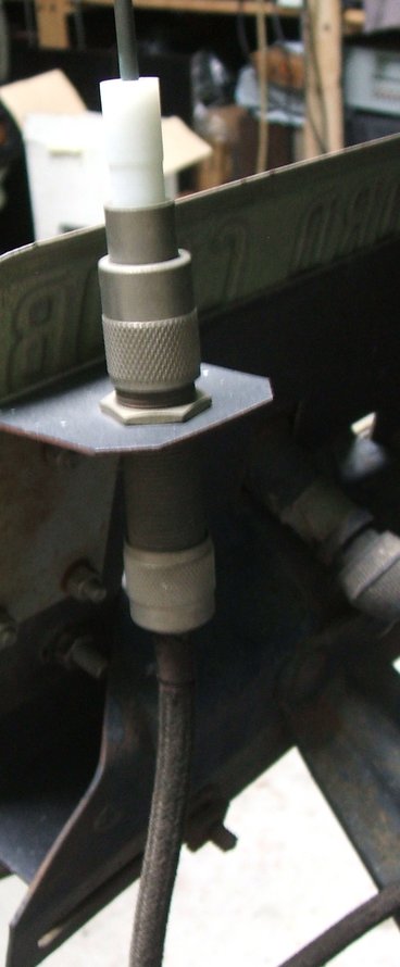
Close up of how the aerial is mounted.
Improved circuit to obtain more volume.
To improve on this would entail adding
some extra gain between the DC volume control stage and the 6AQ5. Simpy
adding an extra triode valve would be a logical start, but there was nowhere
to accomodate it. Either the 6AQ5 or 6CS6 would have to be replaced by
a dual valve. It would be easiest to replace the 6AQ5 with a triode pentode.
The 6BM8 would be ideal, except its power output is not as high as the
6AQ5, and in this application a reduction of this would defeat the whole
excercise. 6GW8 would be a possibility, but being a high gain valve, I'm
not convinced it would be reliable in the long term with regards to vibration.
It's also a valve I don't have a huge quantity of, and the audiophile crowd
have pushed its price up if buying new.
For the operating conditions, 6AQ5 remains
the best choice, particularly with regards its relatively low heater current.
Replacing the 6CS6 with something of higher
gain was the first experiment. The 6CS6 stage provided a gain of 117 times.
Whilst browsing the RCA Tube Manual, I noticed in their tables of RC amplifier
specs, that 6CB6 was mentioned. This was interesting because normally this
valve is known for RF applications. For the DC volume control circuit,
it was actually plug in compatible, and all that needed to be done was
to change the screen resistor to 680K. Results looked very good at first.
Gain was 264 times, and the 6AQ5 could be fully driven under all circumstances.
Unfortunately, the problem of using a
sharp cut off valve became obvious. With a strong signal coming from the
12AT7, and with the volume set low, the distortion was unacceptable. This
is because when the valve is close to cut off, it's working in class B.
That is, the postive cycle of the input signal is amplified more greatly
than the negative cycle.
Type 6BZ6 is a semi-remote cut off version
of the 6CB6. This was a lot better and almost passable. Alas, the distortion
was still sometimes evident. While I did not actually measure the gain,
I did notice that the 6AQ5 could not always be fully driven.
One difficulty with modifying this stage was the 7 pin valve socket. This limited the valve to being a single pentode or triode. That is, except for the 6J6 twin triode. If both triodes could be utilised, suitably high gain might be obtainable. The catch is, the 6J6 has a common cathode. This would cause difficulty since the cathode voltage varies with the volume control setting. Nevertheless, it was found that one 6J6 triode worked quite well as a DC volume control without obvious distortion. Attempting to use the second triode to increase the gain wasn't successful because of the cathode coupling. At this point, it was clear the 7 pin socket would have to be changed to a 9 pin type to allow the use of a valve with separate cathodes.
This wasn't a simple matter, because of where the 6CS6 was located, at the bottom the upright chassis. It would be impossible to get a socket punch or cone cutter in to enlarge the hole. Another option was to move the 6AQ5 to where the 6CS6 had been, and put the 9 pin socket where the 6AQ5 was. This was easily done and the 9 pin socket was installed.
First valve I tried was a 12AX7, as this is the highest gain of twin triodes. Alas, the sharp cut off characteristic was severe. Remembering the 6J6 worked OK, I thought that a lower gain triode should have a better control characteristic. And, so a 12AU7 was tried. This was looking good! Alas, the gain with both triodes in operation was only 114 times; no better than the 6CS6 it was replacing. In view of this, the 6J6 wouldn't have had enough gain even if it could be made to work.
What was needed was a kind of combined
12AX7/12AU7; a twin triode with one section being low gain for the volume
control, and the other being high gain to drive the 6AQ5. Such valves are
not common types, so this idea was immediately discounted.
What about a triode pentode? The 6BL8
has a triode not too dissimilar to a 12AU7, so that was tried next. Things
were looking really good now. A gain of 450 times was more than enough,
and the control characteristic seemed good. Unfortunately, closer observation
revealed all was not in fact well. Even with no cathode bypassing, the
gain was actually too high. At high volume, feedback was evident. A high
frequency oscillation could be heard. Capacitive bypassing didn't get rid
of it, and it was only evident when the super-regenerative detector was
operating. I wondered if it was because the 6AQ5 socket was now close
to the tuned circuit, and there was some capacitive feedback. A small sheild
was made up and placed between the tuned circuit and the 6AQ5 socket and
this seemed to improve things. It still didn't completely get rid of it.
On a few stations it was also noticeable that the distortion was still
there at low volume.
Now it was looking like I'd have to go
back to a 6CS6 kind of circuit, using a pentagrid or similar, to eliminate
the distortion. There were some Philips 10 pin valves introduced in the
1960's for TV use. Type 6V9 was of potential interest as it contains a
triode and a dual control heptode. The 10 pin (Decal) socket fits the same
hole as the 9 pin type. Whilst browsing through one of my Miniwatt
booklets to look at the 6V9 data, I glanced upon the the fact that type
6ES8 is actually a semi-remote cut off type. This is a frame grid twin
triode, intended for cascode VHF amplifier circuits. Before changing the
socket to take a 6V9, I thought I'd just give the 6ES8 a try.
This worked surprisingly well in fact.
With both triodes in circuit, gain wasn't high enough to cause problems
like it did with the 6BL8, and the control characteristic was good. Certainly,
keeping in mind this is not a hi-fi receiver, the distortion at low volume
is not problematic.
Note the small shield near the tuned circuit tagstrip.
One final modification was done and that was simply to add 150 ohm resistors across the vibrator contacts. While the vibrator has been completely reliable over the 13 years this receiver has been in use, inclusion of these resistors is the right thing to do. Also, the 6AQ5 grid resistor was replaced with 470K in line with specifications.
An interesting discovery was made regarding the 82K resistor in series with the tuning control. While rearranging parts on the same tagstrip, I noticed I had used a second hand carbon resistor. Not surprisingly, when I measured it, the value was 105K. Suspicious that this might be contributing to the tuning drift this receiver has always had, I heated it with a soldering iron, and sure enough the resistance increased. I replaced it with a new metal film 100K and the drift became less evident.
6AQ5 where the 6CS6 was, and 6ES8 where the 6AQ5 was.
While the improvement in gain has been
worthwhile, audio output is ultimately limited by the single ended 6AQ5.
Before distortion sets in, power to the speaker voice coil is only 1.5W.
There is no way to increase it, but to use a push pull output, or a larger
valve like 6L6 or 807. This would increase the current drain of the radio
to the point of the battery actually discharging.
A push-pull stage using two 6AQ5's was
subsequently built up for the radio. It increased the audio power to just
over 5W. See
here for the details.