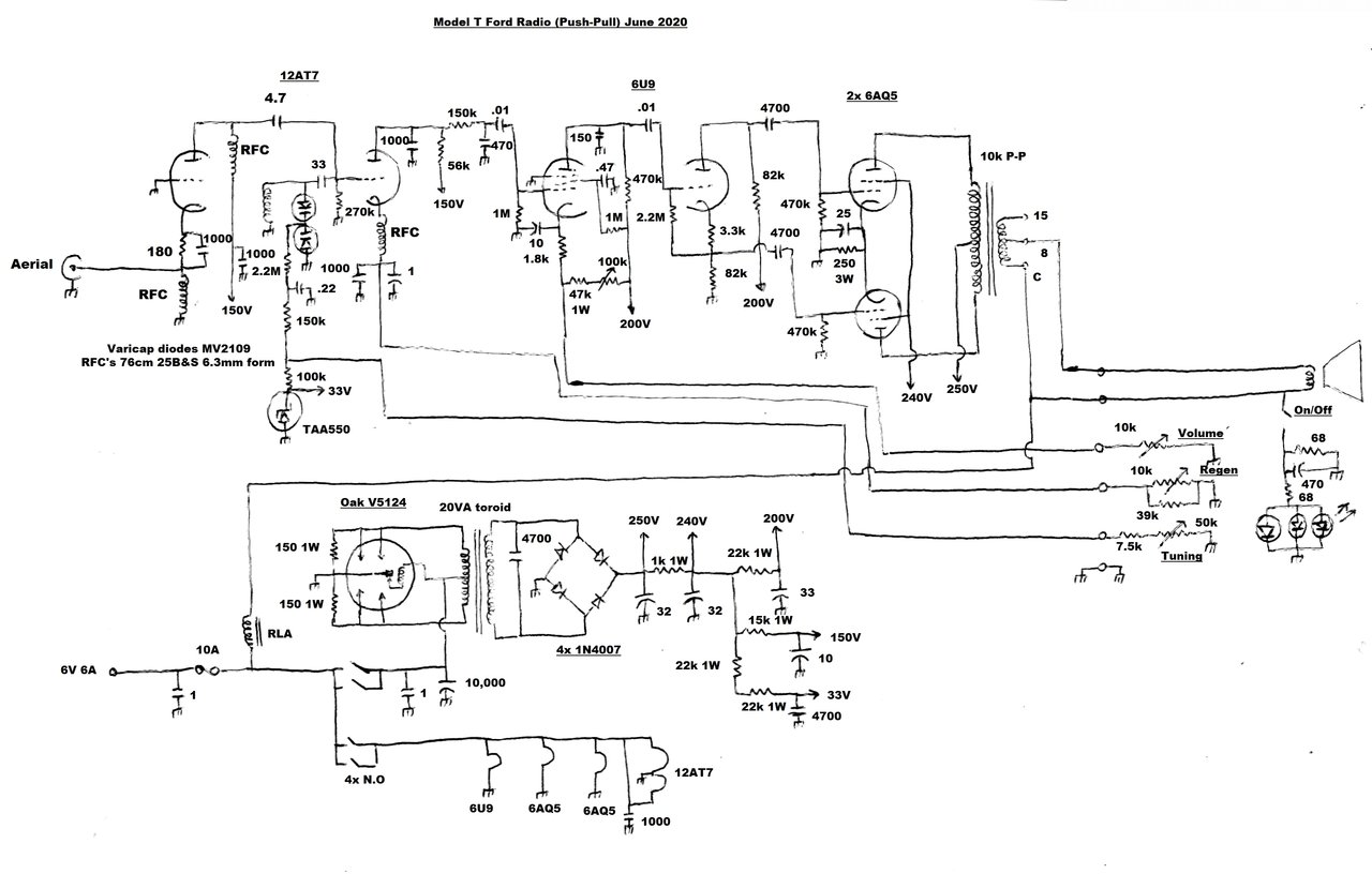
Modified radio now provides slightly over 5W output. Apart from circuit changes, there is a new vibrator and speaker transformer, a 6U9, and an extra 6AQ5.
Modified radio now provides slightly over 5W output. Apart from
circuit changes, there is a new vibrator and speaker transformer, a 6U9,
and an extra 6AQ5.
The Model T car radio has already been described in detail here. This article should be read first to understand the improvements described here. The radio worked well for what it was, except for lack of audio output power to overcome road and engine noise. Briefly, the last modification done to the set was to increase the drive to the 6AQ5, since it was not quite being fully driven by the original circuit.
Single Ended 6AQ5 Limitations.
However, given the single 6AQ5, and the
B+ voltage, the best it could provide was only 1.5W into the speaker voice
coil. This was only just satisfactory for quiet suburban driving, but for
highway driving at 70km/h, it was completely inadequate.
A glance at the 6AQ5 data shows 4.5W output,
so why is the output power in this instance so low? Firstly, the "4.5W"
is the power going into the load; i.e., the primary of the speaker transformer.
Because of transformer losses, what comes out of the secondary winding
to feed the voice coil is less than this. Apparently, it can be as low
as 50% with a lesser quality transformer. Secondly, is the operating voltage.
The 6AQ5 is rated for 250V on the plate and screen, when operated as a
single ended class A output stage.
It's important to realise this "250V"
is the plate to cathode voltage, not the B+ supply, because of the
voltage drop across the cathode resistor and speaker transformer primary.
There will be 12.5V across the cathode bias resistor, and a similar amount
across the speaker transformer. So, as a rough estimate, the B+ needs to
be up at almost 280V. In the Model T radio, it was barely 240V. As will
be shown later, those 40 extra volts do make a big difference.
Thirdly, the power rating given assumes
fixed bias (-12.5V). When bias is provided by a cathode resistor, this
is obviously dependent on total valve current. There is some loss of maximum
power output, since the cathode current is not constant over the normal
power range.
Possible Options.
Seeing as the B+ was not as high as it
should be for best possible power output, thoughts turned to output valves
with lower voltage ratings. In particular was the 6CW5/EL86. With a 200V
plate supply, it can produce 5.3W into a 2.5k load. Total screen and plate
current is up around 70mA.
One catch is the 2.5k load. A speaker
transformer with that impedance is not as common as 5k types, and I had
nothing of the kind in my collection. Initially, I thought it would be
possible to use a 5k to 15R transformer, since the impedance ratio when
used with an 8R load would present a primary impedance of 2.7k. With much
optimism, a 6CW5 was temporarily wired into the set, and an 8R load connected
across the 15R secondary. Alas, power output was only 1.7W. It was also
noted that the B+ had fallen considerably, because of the higher current,
and poor regulation of the power supply. This was only part of the story.
It turned out that using a 5k:15R transformer as a 2.7k:8R was unsatisfactory,
despite the correct ratio. It would appear that there is an optimum inductance,
and this was too much. In fact, an M1120 PA line transformer gave better
results with 2W output, despite not being designed to have DC through the
primary.
Valves like 6L6 and 807 were really out
of the question because of lack of space, and the power supply would not
be up to it in its present form. Besides, a 2.5k speaker transformer would
still be required.
It would have to be a push-pull output
stage.
Some thought was given to class-B operation,
since this would fit in nicely with the power supply. I had seen a circuit
for a transmitter modulator, described in "GE Ham News", where a
12AU7 was supposedly providing 12W with 300V of B+ at 40mA, falling to
15mA with no signal. Similar circuits were known using a 12AX7 with less
power.
Unfortunately, I just could not find any
official information on class-B operation of these valves, and was loathe
to simply accept this seemingly bizarre operation as legitimate, as far
as ratings were concerned. Class-B operation requires an input transformer
to provide grid current, something that RC coupling is not required to
provide for class A operation. Alternatively, a cathode follower can be
used, as was done with the GE circuit. Either way, these extra components
would have to be fitted into the very limited space available.
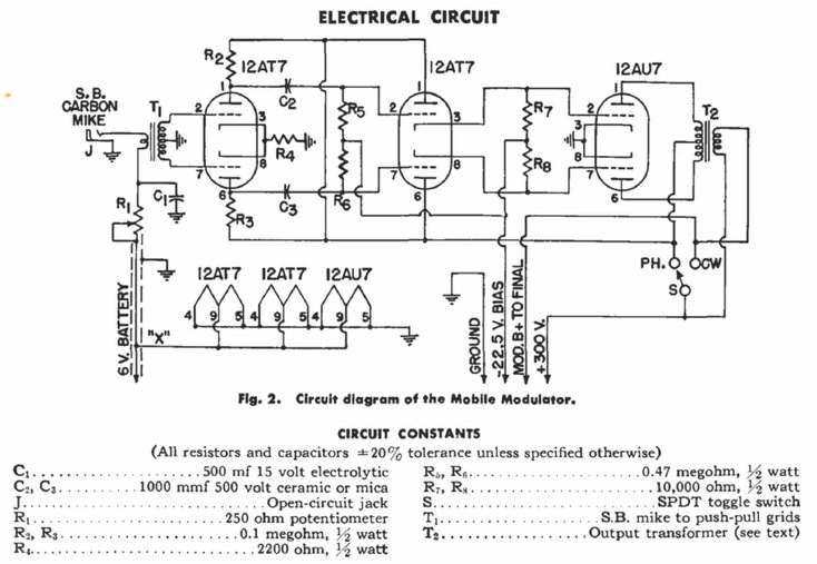
From "GE Ham News" July-August 1950, this shows a 12AU7 working
in class-B.
Nevertheless, a quick test was done using a 6CG7 in class B. Output power obtained was 4.5W with only 40mA B+ at 240V, and -12V bias. I have no idea if the load impedance was optimum or not, but the output was visibly distorted. The 6CG7 was transformer driven from the signal generator.
Push-Pull 6AQ5's.
Now the option came down to a more conventional
push-pull circuit, and the obvious choice would be 6AQ5's given their smaller
size, and lower heater current, compared to larger European 9 pin valves
like 6BQ5 or 6M5. The trade off is a lower sensitivity, but this could
be made up for in the driver stage. The next question would be what to
use for a phase splitter.
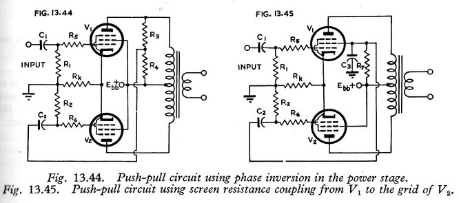
Both methods were tried but were inferior to a separate phase splitter.
The valves must work in class A for full output in these circuits.
One enticing circuit which was once popular
in Australia, was to use an unbypassed screen resistor for the "upper"
valve to provide the out of phase signal for the "lower" valve. See Fig
13.45. The beauty is that the only modification to the radio would be to
install a push-pull speaker transformer, and to find space to install the
extra 6AQ5. This would simply be driven from the existing 6AQ5, which would
now have an unbypassed screen resistor.
The way the circuit operates is quite
ingenious, and relies on the screen grid of a pentode or tetrode functioning
as a defacto plate. If the screen grid is fed via a resistor (R7), a voltage
will be developed across it, in the same phase as the plate. Seeing as
this is the opposite phase of the control grid, the signal can thus be
used to drive the second output valve. By selecting the value of the screen
grid resistor carefully, the voltage can be made the same as that of the
control grid. Typically, the resistor is around 2.5k. C3 is a high frequency
bypass condenser.
A test circuit was built up and tested.
Unfortunately, the simple circuit had two problems. One is that some distortion
was evident in the screen grid drive signal. More seriously was that the
circuit has to work in class A. This means exactly double the current consumption
of a single 6AQ5, which would be beyond the capability of the existing
power supply. However, with a 260V B+ and a current of 100mA, the circuit
provided 6.75W into the voice coil. Attempting to operate the circuit in
class AB improved the current consumption to 55mA, but output was only
2.8W.
Another variation on this theme is a voltage
divider is connected across the "upper" valve's plate circuit (Fig 13.44),
to provide the drive for the second valve. Perhaps because of the layout
I used, there was some instability. In any case, distortion and power output
was no better.
It would seem that a "concertina" phase
splitter, using a triode, would be in order. An extra valve would have
to be added, as well as the extra 6AQ5. This was awkward due to lack of
space, so thoughts turned to replacing the existing 6ES8 voltage amplifier
stage with a triode pentode; the pentode for the DC volume control and
voltage amplifier, and the triode for the phase splitter.
A pair of 6AQ5's were tested with a proper
push-pull input signal. Output was 5.2W with a B+ of 240V. It was found
that class AB operation was excellent, which meant only 50mA of B+ current,
rising to 60mA at full output. This is not much more than for a single
6AQ5 operating in class A, and was the kind of result I was looking for.
Grid drive was 27.5Vp-p. It's more than
for a class A operation, but this is because the grids are being driven
into conduction.
Modifying the Transformer.
Having established that push-pull 6AQ5's
were the way to go, the next thing was to deal with the speaker transformer.
I have a few suitable 10k CT speaker transformers, but all have 15R secondaries.
Since the speaker is 8R, the transformer has to be modified to provide
an 8R tap. The procedure is fairly simple. The laminations are removed
from the transformer first, noting their order. I pile them up on the bench
in the order they are removed. Despite no laminations, the transformer
will work as an air cored type, for the purposes of testing the impedance
ratio. I put 20Vp-p into the full 10k primary. Output was 761mVp-p from
the 15R winding.
The turns ratio, N, is thus 26.28. The
impedance ratio is N squared = 691. Now, if the secondary is 15R, the primary
is 10.36k. So, we have established what was expected.
Next, to find where to put the 8R tap.
The impedance ratio now needs to be 10360/8
= 1295. This results in N being 36. So, if 20V is fed into the primary,
we need 556mV on the secondary. The procedure is now to unwind the secondary
until this voltage is reached. In the case of the Rola B29 transformer,
it's almost two layers of the secondary winding to be removed. A few inches
of wire is looped out for the tap, and the rest wound back on to retain
the 15 ohm option. Once that's done, the laminations are reinserted, and
the transformer put back into its mounting bracket.
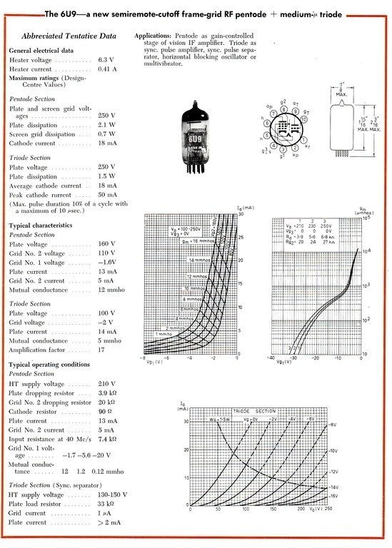
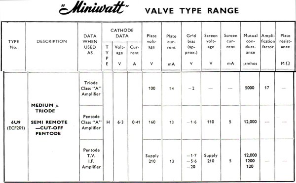
The 6U9 was one of the new Decal series
of Philips valves introduced in 1964 (see "Miniwatt Digest" for July 1964
for details), the others being 6X9, 6V9, and 6Y9. These look like ordinary
9 pin miniatures, but have a 10 pin base. The valves are, in part, high
gain frame grid types, which were designed to reduce the valve count in
a TV set. They were very popular in Australia, and common in sets of Philips,
Kriesler, and HMV design. The precision of design and construction makes
them virtually SQ (Special Quality) types, albeit for consumer use. Europeans
would know these valves in their series heater versions; PCF201, PCF200,
PCH200, PFL200. It's unfortunate that most vintage electronics enthusiasts
overlook television valves.
What attracted me to the 6U9 is the high
gain pentode would take care of the entire voltage amplification, rather
than using two triodes (the 6ES8 used previously). The triode, with characteristics
similar to that of a 6BL8, would be perfect for a phase splitter. Assuming
the control characteristic of the pentode, (similar to a 6EH7) was suitable,
the volume control could remain part of this stage. Remember, the radio
uses a DC volume control to simplify connection to the control head.
The 6X9 is pin compatible, but the pentode
is sharp cut off, similar to a 6EJ7, while the triode is high mu, like
that of a 6DX8 or 12AT7. A sharp cut off characteristic is not suited to
a DC volume control, since distortion is a problem at low volume with a
strong input signal.
If the 6U9 turned out not to have a suitable
control characteristic, there is the triode heptode, 6V9. Here, the old
6CS6 volume control circuit, which was used in the first version of this
radio, could be reconfigured to use with this valve.
The 6U9 was tested first as a phase splitter using the triode. It worked well straight off, and component values are not critical. Importantly, there was no visible distortion. It was possible to get 40Vp-p output with a B+ of 200V. This would be easily sufficient for two 6AQ5's. This type of phase splitter has no gain; in fact a slight attenuation, so all the voltage amplification has to occur elsewhere; usually in the preceding stages. To get the 40V output required an input of 50V.
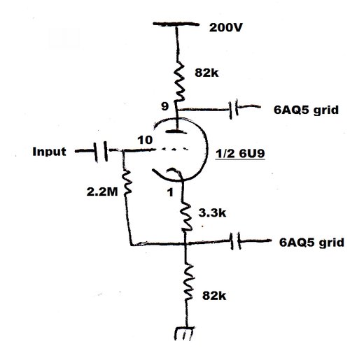
Phase splitter using the 6U9 triode section.
Tests were then done for the pentode. Although
it was never intended to used as an RC coupled audio amplifier, it works
well in this role. Suitable operating conditions were established, and
measurements taken with 100mVp-p fed into the grid. The table below shows
the gain between the grid of the 6U9 pentode, and the output of the phase
splitter. The lower 6AQ5 grid connection was used as the measuring point.
Vk is the cathode voltage of the pentode above earth; i.e., the same as
the grid bias.
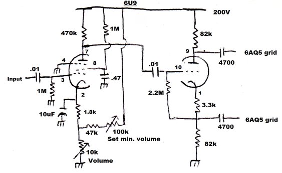
Complete 6U9 circuit to drive 6AQ5's in push-pull.
| Output Vp-p | Bias (Vk) | Gain (Av) |
| 23.7 | 0.47 | 237 |
| 20 | 1.46 | 200 |
| 10 | 2.62 | 100 |
| 5 | 3.28 | 50 |
| 1 | 4.15 | 10 |
| 0.5 | 4.57 | 5 |
| 0.1 | 6.36 | 1 |
| 0.05 | 11.56 | 0.5 |
To briefly recap, the pentode is used as
a conventional amplifier, but since it has a variable mu characteristic,
its gain can be controlled by adjusting the grid bias. Here, the cathode
voltage is adjusted instead, which results in exactly the same effect.
Taking the cathode positive is the same as taking the grid negative, with
a reduction in gain as the voltage goes more negative. The reason for the
DC volume control is because it means only one wire is required to connect
to the potentiometer, and this wire does not need shielding.
The 1.8k sets the minimum bias for the
pentode. A preset voltage divider comprising of a 100k preset and 47k resistor
sets the minimum volume level, when the 10k pot is at maximum resistance
(lowest volume). The screen and plate circuit is conventional, with a 470k
load resistor, and a 1M screen resistor. The screen bypass is higher than
necessary, but 0.47uF was to hand. 0.1uF is sufficient. The control range
is roughly 0-15V across the 10k pot.
Results were very good. The control characteristic
was excellent, without any visible distortion over the control range. It
looked like the gain from the pentode was sufficient not to require any
further voltage amplifying stages.
Testing the 6U9 as a voltage controlled amplifier.
| 1st filter B+ (spkr. trans. CT) | 2nd filter B+ (6AQ5 screens) | B+ current | Power Output |
| 200V | 186V | 52mA | 3.5W |
| 240V | 224V | 63mA | 4.7W |
| 250V | 234V | 66mA idle, 74mA full power | 5.1W |
It's obvious just how important B+ voltage
is when full output is required. The 200V was obtained with 6V input to
the radio. As I discovered, about 400mV was being lost across the fuse.
In fact, the connection to the end of the fuse was almost too hot to touch.
At 5.5A, 400mV represents 2.2W! The 6V supply current is now higher, not
just because of the increase in B+ current, but also the extra 450mA heater
current for the new 6AQ5, and the 6U9 having a slightly higher heater current
than the 6ES8.
400mV being lost across the fuse is significant,
because anything that happens on the 6V side is multiplied 40 times in
the B+ voltage. So, we are losing 16V of B+ because of the fuse. Two possible
options here would be to provide separate fuses for the heaters and vibrator,
thus lessening the drop across each fuse, or to use a higher current 3AG
or blade fuse.
Even so, the original transformer still
can't provide 250V at the current required, with 6V input, and it was already
running as hot as I'd like. There wasn't any problem with it saturating;
it was really that the primary winding wire wasn't thick enough for the
current.
Time to look at another options here.
The best modern transformers for vibrators are toroids. I've used them
in many circuits with excellent results. In this set, a Jaycar 20VA type
would be perfect. A quick check showed that it would fit in the space occupied
by the existing transformer. With the 6V supply, it would require a rewind
of what was originally the secondary. This is no difficulty, and in fact
I did just that with the transformer in the valve
car amplifier.
Not only would the amount of turns need
to be reduced, but in view of the higher current, either replacing
the old secondary with thicker wire, or doubling up on the existing wire.
Toroidal Transformer.
The transformer chosen was a Jaycar MT-2086.
As originally manufactured, the transformer had two 15V secondaries of
164 turns each. Tested on no load with 248.5V input, the secondary was
17V. The transformer has a turns ratio of 14.6:1. There are 164/17= 9.6
turns per volt.
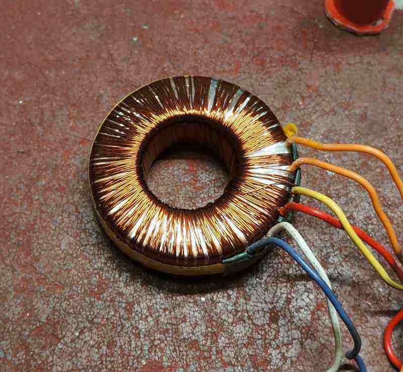
Transformer with outer insulation removed, ready for unwinding the
secondary and counting the turns.
For vibrator use in reverse, the new low
voltage windings (the original secondary) need to be about 4.5V each, to
get 250V under load on the high voltage winding. It is not 6V as first
assumed, because of transformer losses and the vibrator dead time being
about 20%. So, for the new windings, the number of turns is 4.5 x 9.6 =
43.
Allowing for wiring resistance and transformer
losses, I decided to use 40 turns.
The original secondary wire gauge was
really too small for what would be close to 3A flowing through it. I could
have doubled it up, but seeing as toroids are awkward to wind anyway, I
thought it would be easier and neater just to use a heavier gauge. I chose
18 gauge since it's the thickest I had.
One cannot wind a toroid by hand simply
by taking the wire off the reel as required. That is, unless it's a very
small reel that fits through the core! Instead, a length has to be measured
out first. How much to use? Well, one turn requires 85mm, so 40 turns is
3.4m. A little extra was allowed for just in case, and the turns wound
on. Now for the test!
Transformer under test prior to replacing the outer insulation.
It looked promising. With 6V fed into the
input, B+ at the first filter was a little over 250V. The vibrator waveform
was checked in case the timing capacitor needed adjustment, but it looked
pretty close. Interestingly, the current consumption on the 6V side seemed
to be almost 500mA less than with the original transformer. This should
not be surprising given the greater efficiency of the toroid. With that
success, the transformer was duly re-wrapped in its outer insulation ready
for installation.
The fuse was replaced with a 10A type,
and the drop across it was now closer to 250mV, which was acceptable, especially
given now the B+ was more than adequate.
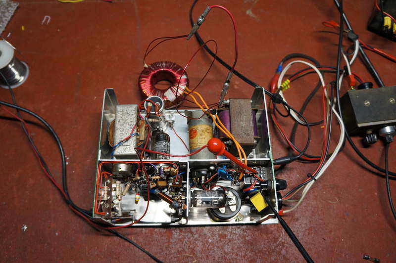
Getting it to Fit.
Alas, with the old transformer removed,
it was found the toroid was actually going to be difficult to fit in the
available space. It couldn't be mounted vertically since it wouldn't clear
the top of the cabinet. With it sitting at a precarious and critical angle
it could be made to fit, but only just! Literally, only a millimetre or
two was between it and the lid of the case. Next, a bracket would have
to be made up.
Set at a critical angle, the toroid only just fits. Note the partition
later fitted between the vibrator and valves.
Problems with the B+ Voltage.
I had noticed that the duty cycle of the
vibrator was slightly low on one set of contacts; around 3.6ms instead
of 4ms. While the set was out I thought it a good idea to readjust the
contacts just to be 'correct'. But, this opened a further can of worms
because now the B+ was too high, if the supply went much over 6V. With
6V input, the B+ was 262V, and if it should rise to 7V, the B+ was 309V.
Taking into consideration of the voltage lost across the speaker transformer
and cathode resistor, the 6AQ5's were at their limit with a B+ of 275V.
This occurred at around 6.4V.
It seemed my choice of 40 turns was an
over estimation of transformer losses, and I should have stuck with 43!
What to do now? I didn't fancy rewinding it again, so thought of using
a resistor in series with the primary. Then I had the brainwave of perhaps
using a thermistor to regulate it; the idea being as input voltage increased,
so would supply current, which would heat the thermistor and thus drop
the voltage. What to use as a PTC thermistor? A light bulb of course! I
found the heaviest filament low voltage bulb I had, a 24V 250W projector
lamp and tried that. Good idea in principle, but too much voltage drop
all the time, although there certainly was a regulation characteristic.
An easier option would be to have a lower current bulb in the secondary
circuit, before the first filter capacitor. I found a 48V 5W bulb worked
well and the input could be raised to 7V without creating excess B+; yet
at 6V, full output power would still be obtained. The killer of this idea
was just that the filament would be too fine to stand up to the vibration
it would be subjected to.
Back to an ordinary resistor in series
with the primary, and I made one out of Constantan wire. It did the job,
and it did actually provide a small degree of regulation.
However, I wasn't happy with the scheme.
The set was already drawing over 6A, and here were a few watts being wasted,
adding to the heat build up in the case.
No choice but to face up to rewinding
the transformer again, and this time I stuck with 43 turns. All worked
out well and it was worth the effort. As a final touch, the vibrator balance
was adjusted; this being more important with toroidal transformers. For
the Oak vibrator, a very slight adjustment of the driving contact screw
will usually achieve this. The timing capacitor was reduced to 0.0047uF,
since 0.01uF was really too high for the long term.
| Input Volts | Input Current | B+ Volts |
| 5.5 | 5.2A | 226 |
| 6.0 | 5.6A | 245 |
| 6.5 | 6.1A | 267 |
| 7.0 | 6.6A | 288 |
The circuit description of the 12AT7 super-regenerative
detector has been covered in the first article, so little more need be
said here. As previously mentioned, it was felt necessary to add a 150pF
condenser at the 6U9 pentode plate, to remove the last of the quench waveform.
While it is too high to be audible, it causes the following stages to be
overloaded, since the signal with quench still present is of higher amplitude
than just the audio signal.
The 6AQ5's are operating in class-AB by
virtue of the cathode resistor being double what it would be for two 6AQ5's
in class-A.
With the heater circuit drawing 1.61A,
the vibrator is drawing about 4.4A, now making the total 6V supply current
about 6A. The vibrator current is on the high side for an ordinary Oak
non-synchronous type (rated for 4A at 6V), but here a synchronous type
is used with the secondary contacts paralleled. This doesn't double the
rating as may be first thought, since the secondary contacts do not open
and close at the same time as those of the primary. Nevertheless, it makes
a useful contribution. Since I had to perform a slight adjustment of the
vibrator anyway, I took the opportunity to set the secondary contacts so
that they did open and close at the same time as the primary. Effectively,
the V5124 is now a V6606 dual-interrupter type. In the extremely unlikely
event the vibrator ever had to be replaced, I would use a V6606, or one
of my communications
types.
As a point of trivia, the Oak V5124 in
this set was the second ever vibrator I obtained back in 1982. It was used
in a few inverters I built up around that time, and then for a short time
in a regenerative receiver, but has permanently resided in this set since
2006. It's further proof that vibrators are not short lived and unreliable,
as so many assume.
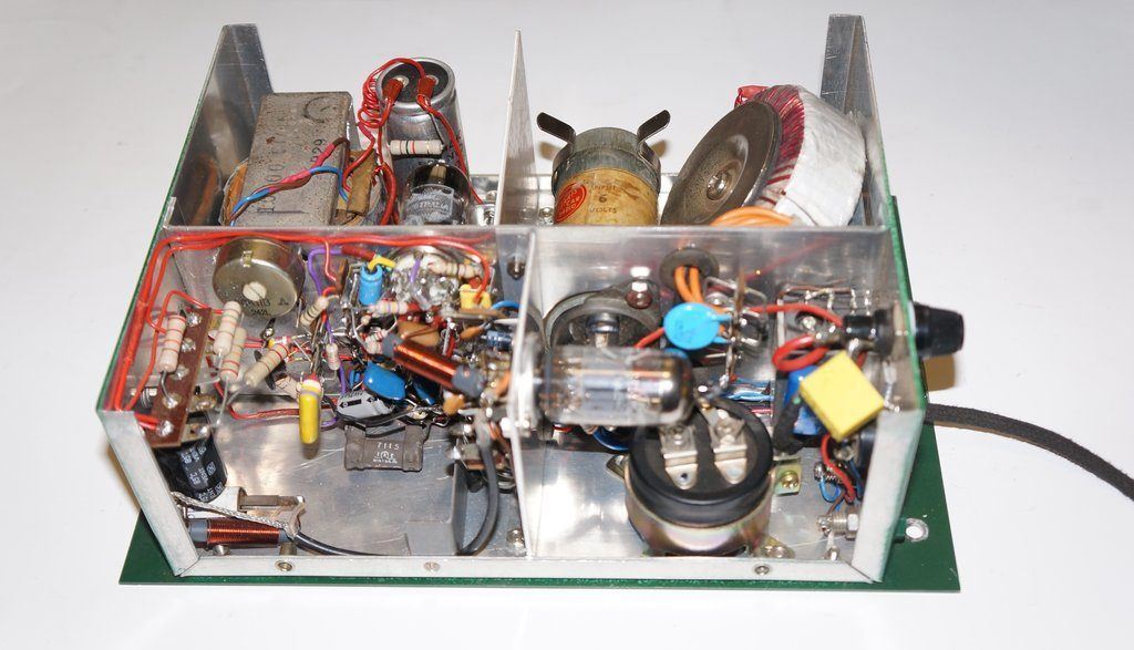
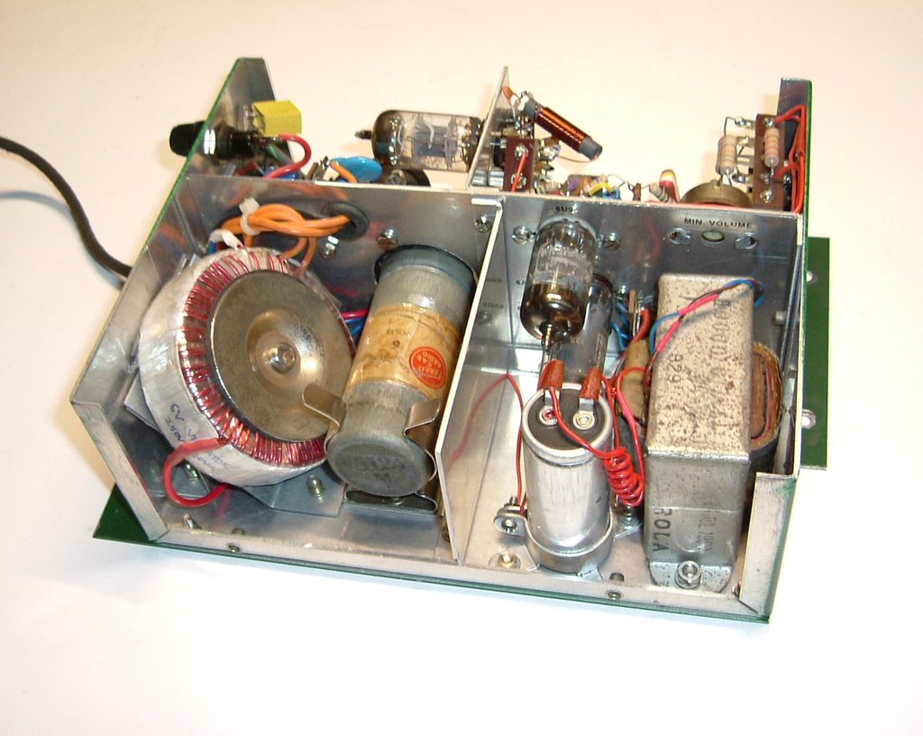
Not much looks different on this side, but wiring is much more cramped
around the 6AQ5's.
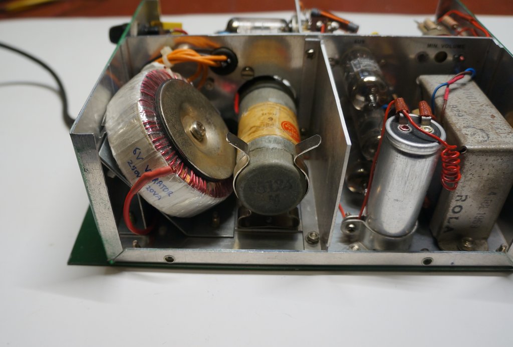
Overheating.
By this point, the receiver was working
well and almost ready to go back in the car. Unfortunately, with the cover
back on the set, the heat build up was excessive. In fact, the top of the
vibrator and the transformer were too hot to touch for any length of time.
Obviously, there is a lot more heat build up with the extra 6AQ5 present,
and that the B+ is higher than previously.
The first thing to do was install some
vents above the 6AQ5's. Three 25mm holes were punched and covered with
aluminium mesh. With the lid on, the heat could easily be felt rising from
the vents. Alas, things were still too hot inside. Next thing was to try
a partition between the 6AQ5's and the vibrator and transformer. A piece
of cardboard was temporarily installed to try the idea, and it worked perfectly.
It would appear that the vibrator was partly being heated by the radiant
heat from the 6AQ5's, as well as the rise in air temperature.
An aluminium divider was made up and installed
permanently. After one hour of running, the transformer and vibrator were
only moderately warm. In fact, with the divider being located right next
to the vents, it appears a chimney effect is taking place, removing the
6AQ5's heat very effectively. The nearby electrolytic capacitor and speaker
transformer are not running very warm at all.
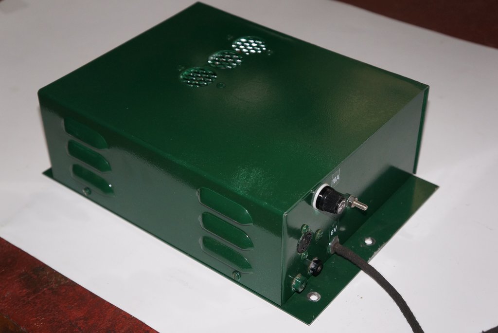
Vents in top of case remove heat from 6AQ5's.
Modulation Hum.
Evident around 100Mc/s was a hum which
was obviously related to the vibrator. It had not existed with the previous
vibrator transformer, so must have been caused by the new toroid. Modulation
hum is quite distinct from RFI caused by the vibrator, in that it is smoother
sounding, and only evident with the receiver tuned to a station. It was
quite easily eliminated with a 0.01uF ceramic capacitor connected directly
at the rectifier output. It appears the wire between the rectifier and
first filter capacitor, which runs across the chassis, had been radiating
RF.
Road Test.
It certainly seemed to have a reserve
of volume it didn't before. The limitation now is the 6" speaker, in that
it points to the floor, as well as being located in the noisiest position
in the car.