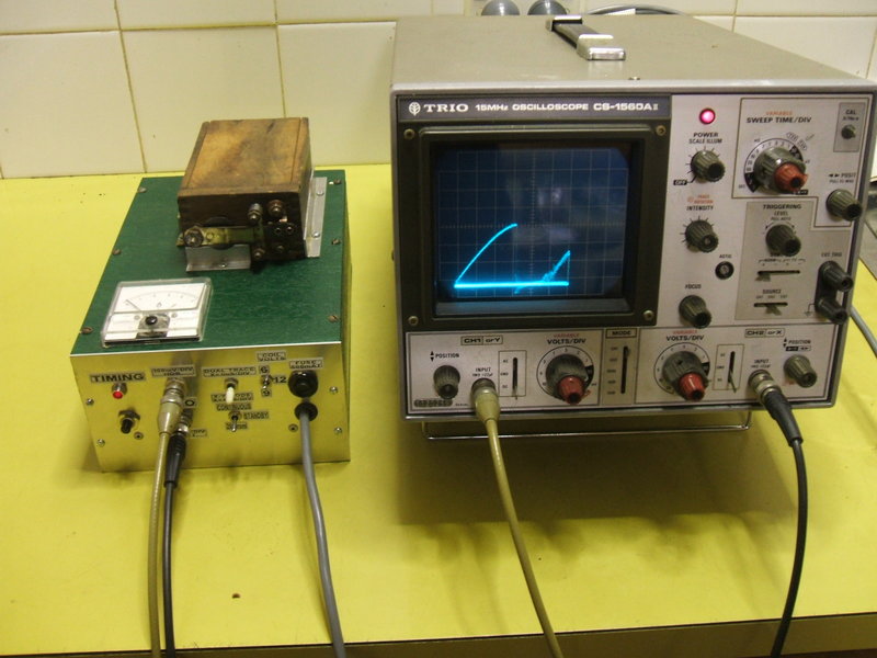
The completed unit set up and operating.
From the time I acquired my Model T, I
was in the difficult position of not having a proper coil tester. All I
could do was to simply use the "Buzz Box" method, and adjust the coils
for an average current of 1.3A at 6V. The limitation with this method of
adjustment is that it does not accurately show coil firing time, or if
there is multiple firing.
Since I've only had 6V battery operation
(the magneto was damaged and later removed), this method of adjustment
did in fact work quite well. However, there was always the uncertainty
- were my coils adjusted as well as they could be?
At the time, the only 'proper' tester
was the Hand Cranked Coil Tester. These were hideously expensive - if you
could find one for sale! Then the Fun Projects "Strobo Spark" tester appeared,
which operated on similar principles, but was much smaller and portable.
While both show multiple sparking, they are not calibrated to show the
firing time.
Of course, being from an electronic background,
it always seemed to me that there should be an electronic method for testing
coils.
First Principles.
There is a certain amount of time between
when the timer makes contact, and when the coil actually fires. When current
is fed into an inductor (the coil primary winding), it takes some time
to rise to its maximum value. The magnetic field also takes a corresponding
time to build up, to where it is strong enough to open the points. Contrary
to what might be initially assumed, the coil does not fire
immediately the timer makes contact.
The firing time (dwell) depends on coil
adjustment. This adjustment primarily consists of adjusting the vibrator
tension, so that the points open when a certain current in the coil is
reached (around 4.5A peak at 6V).
It can be see that if the dwell time of
each of the four coils is not equal, then some cylinders will fire earlier
or later than the others (i.e., some will be advanced and others retarded).
Obviously, the engine will not run as smooth as if the coils all had equal
dwell time.
What was needed was a method of measuring
the coil firing time, and much thought was given as to how to achieve this.
An obvious means to display the result would be with a CRO.
This method of coil testing was not new. It had been used by Montana 500 entrants for some time (which suggests its effectiveness), but little specific information was available. From what I could tell, a Hall effect current probe measured the coil primary current, and the coil was switched by a function generator via some kind of power semiconductor.
I had been thinking of using the current measuring method, and when I discovered a Hall effect current converter IC mid 2012, (ACS712-TELC-20A) the idea of this instrument was born. While one could sample coil current with a low value resistor, I was concerned that any resistance would cause the coil magnetic field to build up more slowly.
The completed unit set up and operating.
First thing was to simulate in car operation
of the coil under test. Essentially, a 6V supply and something to simulate
timer operation at 2000rpm was required. This is the highest likely engine
speed, so the coils would be tested under the most difficult operating
conditions.
Using a CRO timebase triggered by the
simulated timer, and measuring the coil current on the vertical axis, real
time operation could be observed, as if the coil was actually in the car.
In fact, there would be no need for a
timebase in the CRO, since that in the tester could take this function,
eliminating any triggering difficulties.
Seeing as it was simple to implement,
I allowed for 9, and 12V operation as well as 6V. I had been experimenting
with 9V operation of coils (this was provided by a switchmode converter
described here),
and some owners run their coils on 12V.
The ACS712-TELC-20A provides 100mV output
for every 1A that flows through its internal current shunt. Thus, setting
the CRO to 100mV/div. shows coil current in amps per division.
Timer.
Thinking about the simulated timer, what
should the frequency, and 'on' time be? Since the timer runs from the camshaft,
its rotational speed is half that of the crankshaft. So, for 2000rpm at
the crankshaft, the timer is rotating at 1000rpm, or 16.7 revs per second.
The period per revolution is thus 60ms. Although there are four coils,
each is fired only once per revolution.
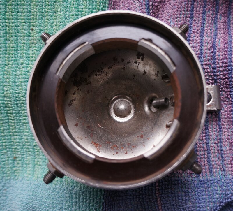
Circumference of a Ford roller timer is 166.5mm. Each segment is
1/8 of that, i.e. 20.8mm.
Using the original Ford roller timer as
an example, each segment is 1/8 of the total circumference. Therefore,
if it takes the roller 60ms to complete one revolution, each coil will
be supplied with current for 1/8 of that time, or 7.5ms.
Since we are interested in only the first
complete firing of the coil, the 'on' time doesn't actually need to be
that long, since the longest time a coil typically takes to fire is typically
3.5ms at 6V. For my tester, 6ms was chosen for the 'on' time since it's
a round number, convenient for displaying on the CRO horizontal axis.
Firing Time.
Now we've got the coil being switched
at 2000rpm. But, what firing time should the coil have? The longer the
time that current is fed into the primary coil, the greater the energy
stored, and the greater the energy released when the points open. Beyond
a certain time, the core will saturate, and no more energy can be stored.
From this point, the current rises rapidly becomes greater and is dissipated
as heat. This time of saturation would thus define the upper limit of dwell
time. Too short of a dwell time will give a correspondingly weak spark.
The Ford coil current adjustment is specified
as 1.3A at 6V, as produced by the magneto on a Hand Cranked Coil Tester,
and measured on a moving iron meter. In practice, using 6V DC with a moving
coil meter is a close enough substitute.
By adjusting a coil thus, we find out
that the firing time is about 3.5ms.
The exact figure is not critical, as long
as each coil for a particular engine is set to exactly the same firing
time.
Multiple sparking is more of a problem with magneto operation, because the coil fires on the rising voltage of a ramp waveform, as opposed to being suddenly presented with 6 or 12V. As the speed of the magneto varies, so does its output voltage, and thus the firing point. This is normal provided the firing points are always consistent, and in fact does provide some degree of automatic timing adjustment. Since the degree of multiple sparking on a misadjusted coil varies with input voltage, it can be seen how erratic firing can occur with a varying engine speed.
We can also see how firing time decreases as supply voltage is increased. This also demonstrates another important thing - increasing coil current to obtain a hotter spark actually reduces performance, since doing so effectively retards the ignition. Best operation of Ford coils at 6V is therefore obtained with lower current settings, and thus shorter firing times. Don't go above the recommended 1.3A. A 'hotter' spark is not necessary - it's more than adequate as is.
Dual Trace Mode.
Here we see the timer vs. coil firing
with the CRO in dual trace mode.
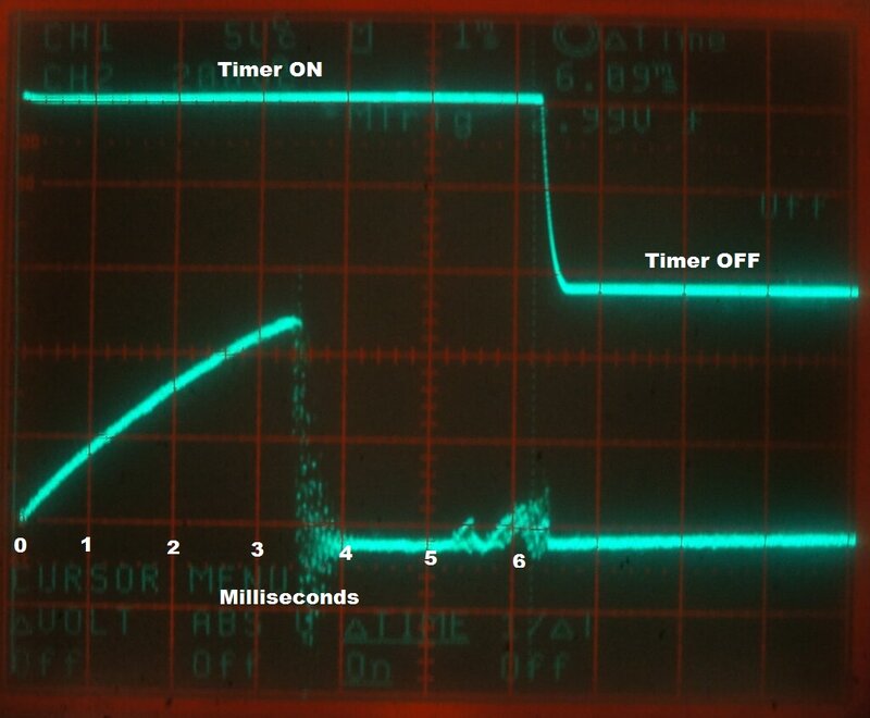
Firing time is 3.5ms for correctly adjusted coil on 6V.
The upper trace shows when the coil is being applied with 6V DC (equivalent to when the timer makes contact), and the lower trace is the current waveform of the coil. Each horizontal division is 1ms. Each vertical division is 200mV on the CRO, which translates to 2A of coil current, per division. So, this coil takes 3.5ms to fire, at a peak of about 5A. The points have closed again at around 5.3ms, and current can be seen to start building up, but the timer switches off well before the coil can fire again.
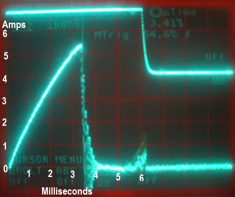
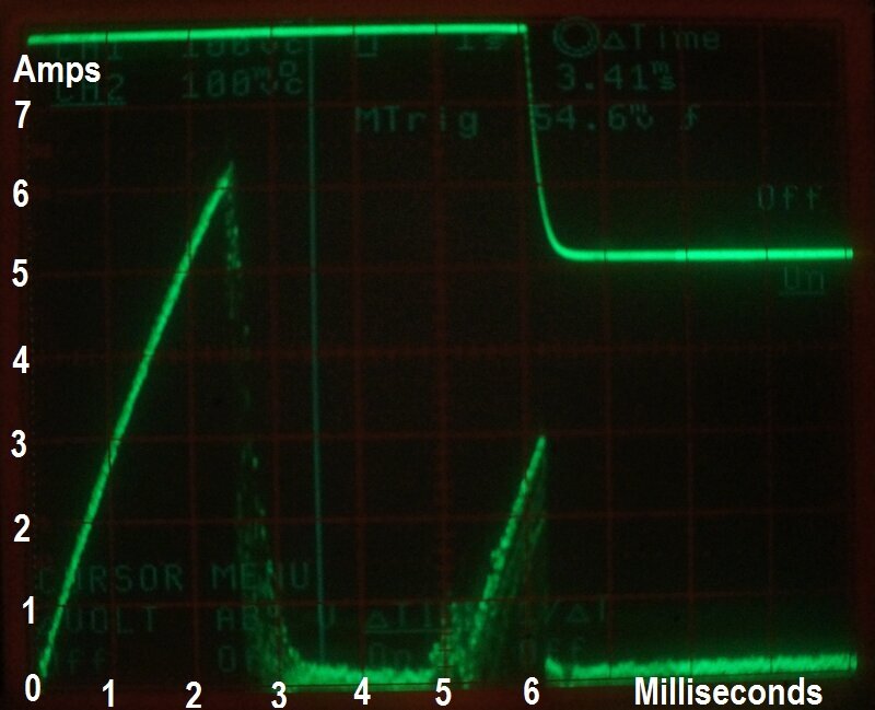
6V Operation of Coils.
In this example, firing time is 3.5ms,
and peak current is about 5.4A.
9V Operation of Coils.
At 9V, firing time is reduced to 2.5ms
and peak current is about 6.2A.
12V Operation of Coils.
When the coil supply is switched to 12V,
we see a further reduction in firing time and increase in peak current.
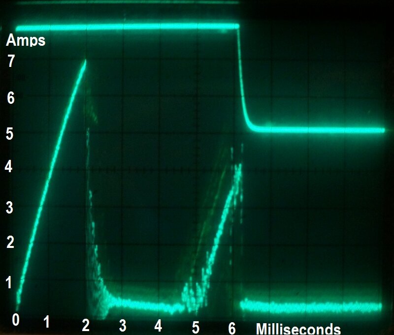
The firing time is now 2ms. Peak current has increased to 7A. This clearly demonstrates that for successful 6V coil operation at high engine speed, the timing must be advanced more than it would be on 12V, to get the same high speed performance. 9V operation causes the coil to fire in between where it does on 6 and 12V.
X-Y Mode.
One difficulty with anything electronic
and
Model T Ford coil, is the amount of energy radiated by the coil. This tester
is no exception, and in some instances there is difficulty in triggering
the CRO, particularly with 9 or 12V testing, because of the high peak current.
In fact, with one CRO used with the tester,
triggering was evident even with the probe short circuited!
To solve this problem, the tester incorporates
its own ramp generator, which drives the X or horizontal axis of the CRO,
substituting for the CRO's timebase and triggering. The ramp generator
is calibrated for a 6ms period.
When X-Y mode is used only the coil current
waveform is displayed.
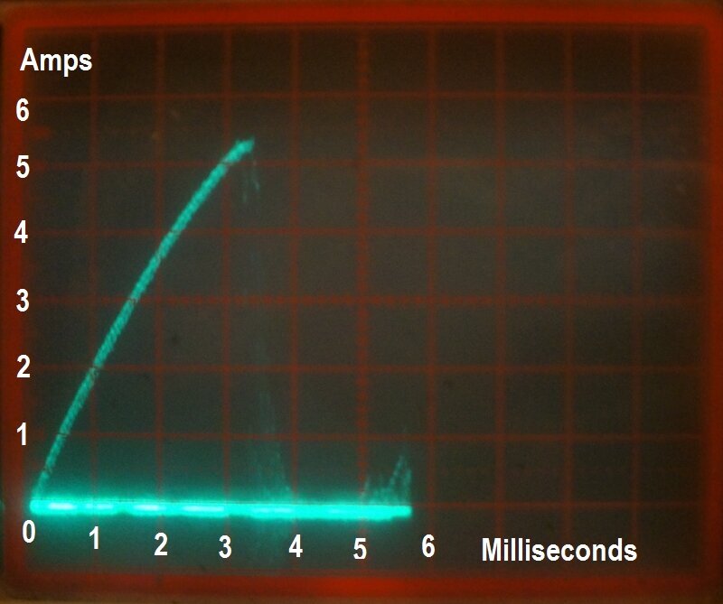
Since the linearity of the internally generated ramp is not perfect, the graduations between 0 and 6ms are approximate. In this instance, the coil tested in X-Y mode is shown to fire at 3.3ms on the scale, even though in reality it was set to 3.5ms as in dual trace photos. This in itself is not a problem, provided that all coils in a set are adjusted either in dual trace or X-Y mode, but not a mixture of both.
Multiple Sparking is Shown.
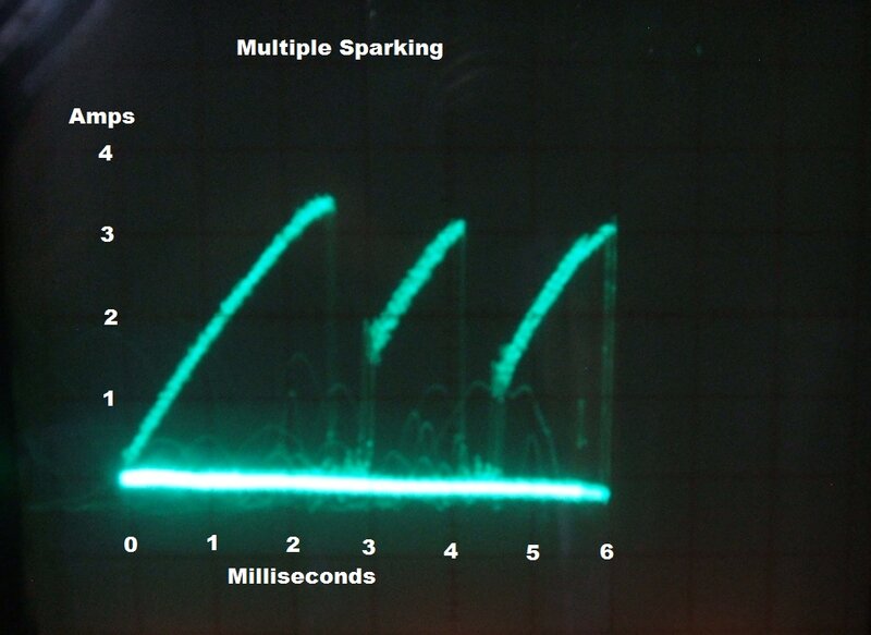
Note that peak current is now only about
3.4A. The sparking energy is now being dissipated over at least 6ms instead
of being concentrated within 3.5ms. Thus, we see multiple sparking robs
the initial spark of energy it could have otherwise had. The average current
shown on the meter does not change when a coil is misadjusted this way,
which again shows the limitations of the "buzz box" method of coil adjustment.
If a coil displays this kind of waveform,
the upper cushion spring is stuck or needs adjustment. The coil under test
was deliberately made to multiple spark by sliding a paper clip over the
upper point cushion spring.
Erratic Firing.
If evident, this shows up as a jitter
in the waveform, with the firing time fluctuating. Worn and eroded contacts
often cause this problem.
The Circuit.
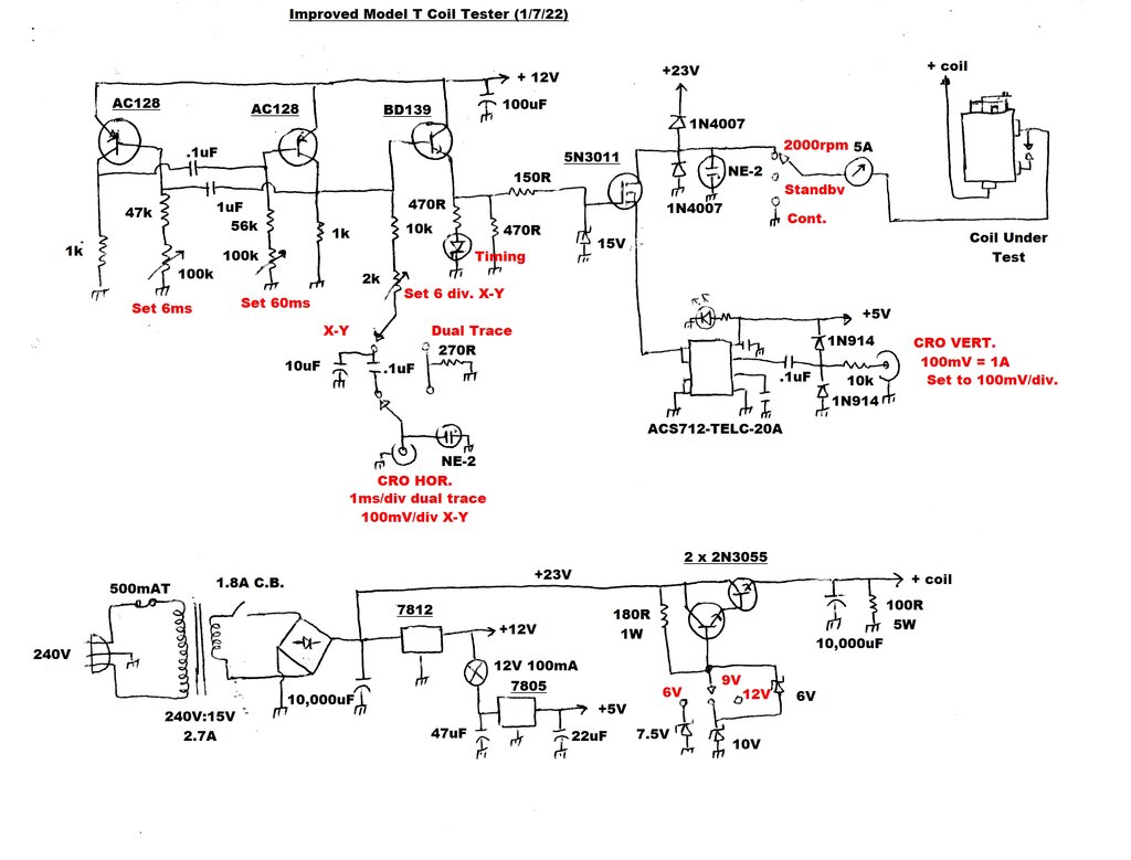
Improved circuit replaces the 2012 design.
Timebase.
This is the heart of the unit. Initially,
I tried various IC circuits. However, radiation from the coil caused erratic
operation, even if placed several metres away. Bypassing, etc., did nothing
to improve the situation. I tried a 2N2646 UJT which again was troubled.
I went so far as to try a relay in astable mode, but the problem was that
anything with mechanical contacts has contact bounce, and this gave an
erroneous display. What I needed was a low gain oscillator. Indeed, using
a couple of audio type germanium transistors solved the problem. I used
AC128's. Not only are they low gain (compared to modern silicon types),
but bandwidth is limited. So, I figured the circuit should be less susceptible
to triggering. Indeed it was, and there was rock steady oscillation regardless
of what the coil was doing. The oscillator is a simple cross coupled multivibrator
with different R-C combinations in the two base circuits. This provides
the asymmetrical duty cycle required. For calibration, trimpots are provided.
The output of this drives a BD139 emitter
follower, and then a 5N3011 MOSFET, which is used to switch the coil. Given
the few hundred volts that may appear across the 5N3011 when the coil is
switched off, a diode is used to prevent any negative voltage appearing,
and another diode clamps the back EMF to 23V. Finally, although not needed,
a neon bulb clamps the voltage to about 90V.
Originally, a 2N3055 was used to switch
the coil, but it was found that the saturation voltage was excessive at
higher peak currents. Testing current was limited to about 4.5A before
the coil supply voltage dropped. With some coils this was sufficient, but
others could not be adjusted properly. To avoid the difficulties of increasing
the 2N3055 base current, a MOSFET was then chosen as the switching device.
Initial experiments showed this to be completely effective, but with a
MOSFET rated at 60V, it was soon destroyed by the coil's back EMF.
The MOSFET used in the final design is
rated at 300V. Additionally, a diode was added to clamp the back EMF to
the 23V supply rail. So, in theory a 60V MOSFET could still be used. The
neon lamp is a legacy of the 2N3055 design and is not actually required.
A 15V zener diode protects the MOSFET
gate against negative or excess positive voltage.
A LED shows the timing pulses, and a timebase output is provided for the CRO second channel, or the X axis, when used in dual trace mode. Output voltage is attenuated by the 270R so that the X axis CRO amplifier can always be left on 100mV/div. The vertical amplifier can be set to DC coupling to avoid showing a tilted timing waveform. The CRO is triggered from this pulse when in dual trace mode. An NE-2 neon bulb prevents excessive voltage from damaging the timebase circuit, or CRO input, should it somehow be fed back in from an operating coil.
Current converter.
Based on a ACS712-TELC-20A, this converts
1A of current flowing through its shunt to 100mV output. Thus, by setting
the vertical channel to 100mV/division, we can read off 1A of coil current
per division. Note that there are several different versions of this IC
rated for different maximum currents. However, only the 20A version has
the direct 1A to 100mV ratio.
The IC is surface mount. While I was prepared
to make a PCB for it, I discovered it was cheaper to buy the whole thing
already on a small PCB on eBay. This was about a third of the price of
buying just the IC locally! So that one side of the current shunt is always
earthed, it is placed between emitter of the MOSFET and earth. This is
done to again minimise high voltages getting in the wrong places.
There is a DC offset on the output which
means the display may be off scale when set to 100mV/div. So, it is AC
coupled it with a .1uF. We don't need the DC component for this application.
Protection from any high voltage nasties is afforded by the 2x 1N914's
and limited by the 10K resistor. It is all too easy with a buzzing Ford
coil nearby for the wrong thing to accidentally happen!
X-Y Mode.
The 6ms pulse is converted to a ramp waveform
by means of the 10K and 10uF. A 2K trimpot allows for calibration of output
level such that 100mV per division when fed into the X amplifier, corresponds
with 1ms per division. In other words, the horizontal trace is set for
6 divisions, showing the 6ms period.
However, because the waveform is obtained
with a simple R-C circuit, the ramp is not completely linear, although
still very good. This means that although the trace is 6ms long, the calibration
of each division in between 0 and 6ms is not completely accurate.There
is about a 200us discrepency around the 3.5ms region of the trace.
A constant current source could be used to charge the 10uF capacitor to
overcome this.
Because of the DC offset, a .1uF is in
series with the output. Dual trace mode should not be used when an actual
measurement of the firing time needs to be observed.
If you find that your CRO triggers reliably
in dual trace mode on the 12V setting, the X-Y mode circuitry could be
left out.
Accuracy.
Like any analog CRO display, the accuracy
of this instrument depends not only on the calibration of the CRO, but
also how the operator reads the waveform. Parallax error, and the accuracy
of the X and Y shift controls have a bearing on this. Also, it must be
remembered that both the tester and CRO use an RC timebase which is susceptible
to drift. As the firing period is displayed in less than half of the eight
divisions of the CRO screen, the resolution is less than it could be if
the timebase was expanded. Because the output of the current converter
IC is AC coupled, it means the Y axis 0V level changes slightly depending
on the waveform. Thus, it is necessary to check this on each coil test,
if an accurate current reading is required. Possible improvements would
be to use a crystal locked, or mains frequency derived timebase, with it
expandable over more of the screen. Also, DC coupling into the CRO from
the current converter IC, with DC offset correction would improve current
measuring accuracy. For X-Y mode, the linearity of the ramp generator would
be improved with a constant current source to charge the 10uF capacitor.
Nevertheless, the instrument in its present form is quite sufficient for
the task, and far more accurate than any mechanical tester.
Power Supply.
A standard 15V transformer, rectifier,
and filter circuit provides around 23V unregulated. A large capacitor of
10,000uF is used to help cope with the spiky high peak current drawn by
the coil. Because a faulty coil may present an excessive load, a 1.8A circuit
breaker is connected in series with the rectifier. It is on the AC side
to provide protection should the rectifier short out. Further protection
is via a 500mA fuse for the transformer primary.
A 7812 provides 12V for the timebase.
This also feeds the input of a 7805 which powers the current converter
circuit. Note the 100mA bulb in series with the input of the 7805.
This was included to limit the current
should the ACS712-TELC-20A lock up. When this happens it draws about 250mA
and gets hot - not good! The first time it happened I thought the IC was
dead, but surprisingly was totally OK at next power up. I figured it would
be wise to limit supply current. This "locking up" problem sometimes occurred
with the breadboarded prototype but has never occurred with the finished
built up model. I found that if the coil was run continuously the radiation
from the coil could cause this to happen, and was no doubt due to less
than optimum earthing and circuit layout.
The coil under test is powered from a
regulated 6, 9, or 12V via a standard zener diode and emitter follower
circuit. The zener voltages chosen allow for the base emitter voltage drop
of the regulator transistors. For improved regulation, the series transistors
are wired as a Darlington pair. This means less fluctuation in current
drawn from the zener regulator. Some may wonder why I've used another 2N3055
to drive the 2N3055 series pass transistor, when the base current required
is so small. I've learnt years ago that if this type of power supply suffers
from an overload that destroys the series pass transistor, it often takes
the driving transistor with it. With the driving transistor rated at 15A,
that won't happen here.
Final filtering is done again by a 10,000uF
capacitor to present a low impedance, high peak current capability, supply
to the coil. A 100R 5W resistor is across the supply output to prevent
any high voltage nasties getting in (the EHT output of a Ford coil would
drop to virtually zero if presented with a 100R load). It also ensures
a load when the coil is not firing.
Construction.
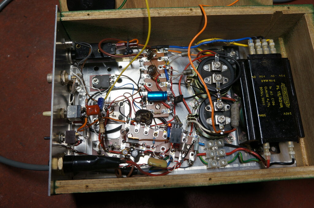
Note the simple aluminium chassis and tagboard construction.
The circuit was built on an aluminium chassis which slides into a wooden box. On this is mounted the meter and coil connections. I use springy brass strips to make contact with the coil terminals, while on the opposite sides angle aluminium provides a backstop for the coil. To do the job quickly and simply, everything was assembled on tagboards and connected point to point. The 2N3055's were mounted in chassis mount sockets. The front panel is attached to the chassis and contains the user controls.
Calibration.
Simply connect the timebase output (CRO
HOR.) to the vertical channel of a CRO, set to 100mV/div. vertical, DC
coupling, and 1ms/div. horizontal, and the switch in 'dual trace' mode.
The two timebase pots are set to provide a total time of 60ms with a 6ms
duty cycle. It is quite possible there might not be enough adjustment given
use of different transistors, or normal component spreads. If so, changing
the values of the two base capacitors will fix this.
Next, switch both the tester and CRO to
'X-Y' mode and set the 2K pot for 6 divisions horizontally. There would
be no objection to setting the duty cycle to 7.5ms to exactly emulate the
roller timer, if this is your preference.
Using the Tester.
The coil is statically set up in the usual
way, with points at .031" and upper cushion spring at .005". See this
article for more detail. Then, with the unit on 6V and "continuous",
the coil is set to draw an average of 1.3A by means of adjusting the vibrator
tension. This is the standard "buzz box" adjustment which provides an initial
starting point to get the coil going.
Limitations of non-electronic testers.
Originally, the best method of setting
Model T coils was to use a hand cranked coil tester. The technology at
the time was well before electronic methods were practical.
The Hand Cranked Coil Tester shows multiple
sparking, evident by more than one spark close together on the sparking
ring, as the tester handle is cranked.
However, the simple ammeter only gives
a broad idea of coil current, and as the electronic tester shows, optimum
coil current for one coil is not necessarily the same as another.
Unless the tester is calibrated, it is
not known what the actual firing times of the coils are. Thus, it is hard
to create a matched set of coils with such a tester. The mechanical tester
does not contain a timer, so one could argue it does not provide
the same operation as that of a car ignition system. The coil is presented
with a slowly rising voltage, rather than being suddenly hit with a higher
voltage, as when a timer is used.
Popular amongst Model T owners are the
simple "buzz box" testers - so called because they usually consist of a
wooden box, into which the coil is placed, and powered up from 6V.
A continuous spark occurs, and the rms
or average primary coil current is measured by an analog meter. Users are
instructed to set to 1.3A at 6V. Unfortunately, as each individual spark
cannot be observed, there is no way of testing for multiple sparking. As
with mechanical testers, the meter reading cannot display firing times.
Nevertheless, this kind of tester will
get a set of coils going in an emergency. Just don't expect optimum operation
from them.
So, you'd like your own electronic
tester?
For those who are technically inclined,
the tester described here is easy to build with mostly common parts. Those
not into vintage electronics may be unfamiliar with germanium transistors,
but they are still available with a bit of searching. Similar types include
AC188, 2N185, OC74, 2SB56, 2SB172, and so on, which should all work. Basically,
they are a type that was used in the audio output stage of many portable
transistor devices in the 1960's and 70's. If you already have a buzz box
tester, the circuitry described here can be added on, saving some construction.
Unfortunately, I am not in a position
to manufacture the testers or supply parts. However, an excellent alternative
which is available for sale is the ECCT.
The ECCT.
Those who follow the MTFCA
forum would have seen mention of the "Electronically Cranked Coil Tester".
It was, coincidentally, developed at around the same time as my design,
but completely independently. The principle of operation is the same, but
that's where the similarity ends. Unlike my design, the ECCT is designed
for use by Model T owners who are more comfortable with mechanical things,
than electronic. Instead of a CRO, the display is via a set of LED's which
show any coil setting errors. For the technical user, an optional computer
interface is available which shows a more detailed graphical result. It
shows all the coil operating parameters while being fired. Furthermore,
there is a capacitor tester and an optional magneto tester. It is basically
a comprehensive Model T ignition system analyser.
I've had opportunity to try one out, and
to come to the conclusion that this is the "must have" Model T instrument
of the decade is an understatement.
This is a truly revolutionary design,
which for the first time allows any Model T owner to set their coils correctly.
It is compact, elegantly designed, and can be run off a 12V SLA battery
for portable use. See my review of the ECCT here.
For further details of the ECCT, please
visit its official website here.