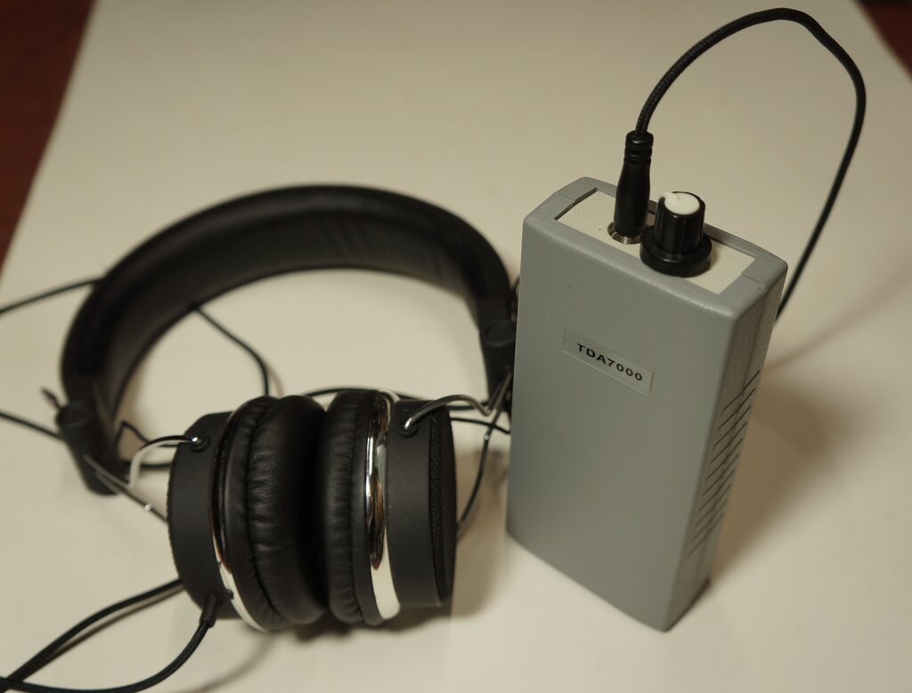
Complete and ready for portable VHF FM listening.

Complete and ready for portable VHF FM listening.
This kit was sold by Jaycar (cat. no. KJ-8238) as part of their "Short Circuits" series of projects. "Short Circuits" was a set of three books, along the lines of the old Dick Smith "Funway Into Electronics" series, intended to teach electronics by building various simple projects. The projects were designed by Silicon Chip. This TDA7000 FM receiver is described in Volume 2, project 21, under the heading of "Personal FM Radio". As with the DSE Funway kits, one was required to buy the book to get the instructions, since they were not supplied with the individual kits. In later years, the books were downloadable from the Jaycar site. Volume 2 is available here.
Like all good things, the kit was discontinued, presumably because of the TDA7000 becoming obsolete. Despite this, TDA7000 IC's are still available from Chinese eBay sellers at the present time (January 2025).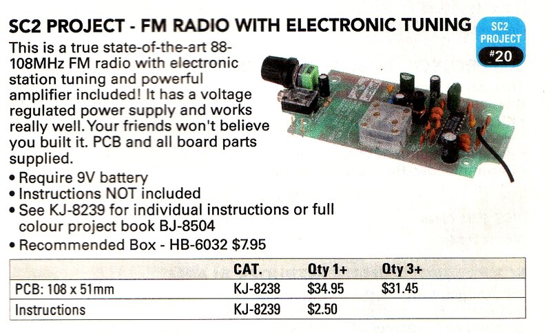

The Design.
The receiver is a headphone only design,
and intended to be mounted inside a HB-6032 plastic case. This makes a
convenient handheld unit, which, with the location of the tuning control,
is quite ergonomic to use. It will also fit a shirt pocket. A headphone
socket and volume control is provided at one end of the case, and a trailing
wire aerial at the other end. No mechanical on/off switch is used, with
this function instead performed by removal or insertion of the headphone
plug. The power supply is a 9V battery. Since the TDA7000 works down to
4.5V, this receiver is an ideal way to use up 9V batteries which no longer
work in voltage critical applications like smoke detectors or digital multimeters.
It has been well thought out, and is a
very elegant design.
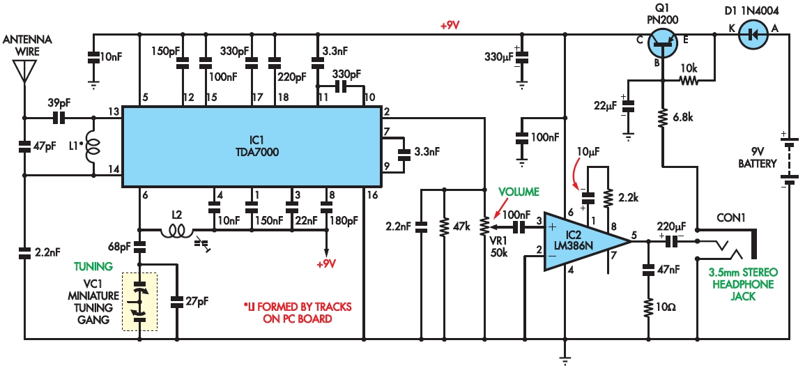
For the most part, the TDA7000 part of the circuit is as per the
Philips application notes. There is a minor error regarding the tuning
capacitor earthing.
The TDA7000 has been described in detail here. Briefly, it is a superhet FM receiver IC for operation up to 110 MHz. What makes it unique is the 70 kHz IF, which allows conventional audio type op-amp filter circuits to provide the gain and selectivity. Thus, coils or ceramic filters are eliminated. Only one coil is actually required, which is that of the local oscillator. A second (optional) coil provides broad RF input filtering. Because of the 75 kHz deviation of the FM signal, it can be imagined that distortion would occur with a 70 kHz IF. To avoid this is a 'Frequency Locked Loop', which compresses the deviation to 15 kHz, by modulating the local oscillator with the detected audio signal. The TDA7000 also features a muting or squelch circuit, and an artificial noise source to make the receiver still sound alive while tuned off station. These two features can be enabled or disabled as required.
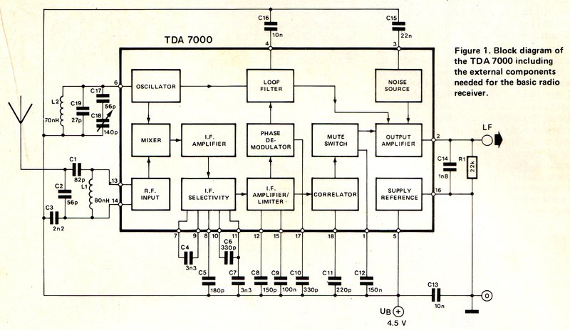
Simplified block diagram of the TDA7000.
A standard plastic type of tuning condenser intended for MW superhet receivers is used, with a local oscillator section of about 60pF and an aerial section of about 160pF. Many other TDA7000 designs do likewise, with the lower value local oscillator section used for tuning the TDA7000's local oscillator. Since 60pF is too high for tuning the VHF FM band, it is padded out with a series capacitor. Interestingly, the Philips application notes show the higher value aerial section used instead, with a series 56pF capacitor. The higher the value of the variable capacitor and the smaller the series padding capacitor, the more non-linear is the tuning action. Stations at the low end of the band are spread apart while those at the high frequency end are cramped together.
This design is unconventional in that the two capacitor sections in series. This should present a more linear tuning action, but the problem is that the shaft and moving plates are not earthed. Hand capacitance could be problematic with the shaft live at RF. Additionally, the 9V battery is right up against the tuning condenser, and could also have a capacitive effect with the live moving plates.
The oscillator coil is adjustable with an F29 ferrite slug, as was done with the Silicon Chip, November 1992, and Electronics Australia, June 1988 designs. As with the EA design, the RF input coil is actually an inductance etched on the PCB, and I suspect was the source of inspiration here.
As with most TDA7000 receiver designs, the ubiquitous LM386 provides audio amplification. Although the receiver is intended for stereo headphones, there is no reason it cannot drive an external speaker instead.
Another undesirable aspect of the design
is that the headphones are wired in series, so that the drivers are out
of phase with each other. This can give an unnatural effect, since one
driver is delayed by 180 degrees relative to the other. With loudspeakers,
the effect is that of largely cancelling the bass response.
The reason for this method of connection
is due to the power switching. The PN200 transistor switches the 9V supply.
This is a PNP type, so when base current flows to the negative rail via
the 6.8k resistor, the transistor switches on. In this instance, the 6.8k
resistor is connected through the right channel of the headphones to negative.
When the headphones are unplugged, no base current flows, and the transistor
switches off, disconnecting the 9V supply. The 22uF ensures that any audio
signal is bypassed. Although I'm sure it was never intended, a mono plug
can also be inserted, and in this case, the 6.8k will be connected directly
to negative.
Normally, for mono use of stereo headphones, the left and right channel are connected in parallel to the audio source, and the sleeve connection of the socket is earthed. Obviously, this would mean the supply would always be switched on, if this was done here.
A perhaps minor thing to note is the audio load resistor connected to pin 2 of the TDA7000. The data mentions 47k for a 9V supply, and 22k for 4.5V. Seeing as this set will be used with run down 9V batteries, I did not bother investigating what the practical difference is between the two resistor values. The 47k across the volume control could be omitted for 9V operation, however.
Building the Kit.
I built up the kit as per the instructions,
with the idea of modifying it, if my suspicions about its design 'limitations'
turned out to be problematic. My initial impression was not good. The RF
performance was not as it should be, with signals cutting in and out due
to the squelch. I am in a good signal area for VHF reception, and this
was not what a good TDA7000 receiver should be like.
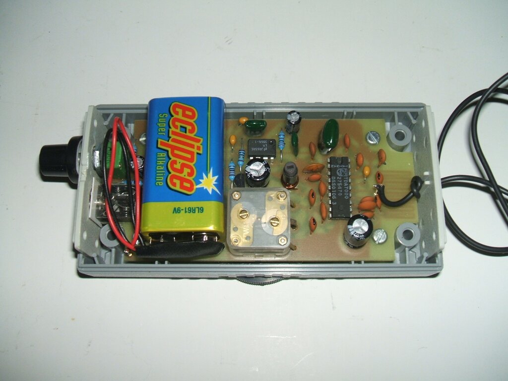
Kit as originally constructed. Note the wire aerial.
1. RF Performance.
Even though the squelch was enabled by
default of the design, the sensitivity should have been a lot better. The
hand capacitance effect of the live tuning condenser shaft did not turn
out to be problematic, mainly because of the isolation provided by the
plastic knob. But, I still didn't like it, and it is not good design. Because
of the way the PCB has been designed, it was better to short out the local
oscillator section and use the aerial section to tune the receiver. This
was because an undesirable length of wire would have to be run to the local
oscillator section. Had the tuning condenser been mounted 90 degrees turned
to the left, it would have been easy to use the local oscillator section.
I found that the ideal padding capacitance was 33pF, so this value was
installed in place of the 68pF.
A slight error in the Jaycar circuit shows the tuning condenser earthed to the negative supply, but the Philips application notes show it earthed to the positive supply. Wondering if this was part of the problem, I investigated closely and found that in actual fact, the PCB was correct, and the tuning condenser is earthed to the supply rail, as it should be.
2. PCB Design.
One aspect of using the TDA7000 often
overlooked is that the PCB design is very important. While the negative
supply rail is at RF earth, and it shouldn't make a difference whether
the tuning condenser is earthed to that or the positive rail, the TDA7000
can be critical in this regard. When I see people build up TDA7000 circuits
on solderless breadboards, or various matrix or Veroboard constructions,
it is a disappointment knowing that such constructions won't work to this
IC's best ability. Experience has shown that the closer to the Philips
PCB design the circuit is, the better it performs.
With the tuning capacitor shaft now at RF earth, the performance was still no better. Keeping in mind the PCB design, which while good, was still not quite exactly as per Philips design, I remembered the supply bypass capacitor which should be as close to pin 5 as possible. Best results can be had by connecting this across the supply under the IC. To this effect, I soldered a surface mount 0.1uF across the supply tracks. This still didn't provide the performance I was looking for.
Next was the tuned circuit itself. I didn't like the amount of track inductance between the supply rail where the oscillator coil is actually connected, and the earthy side of the tuning condenser, also at supply rail potential. It was quite a round about path despite the two connections actually being very close to each other. It only took a short link from the coil positive connection to the tuning condenser earth. This changed everything, with performance much improved. The surprising thing is this connection could have easily been part of the PCB. To give an idea of how much the original PCB layout affected performance, once the missing link was in place, the local oscillator coil had to be tuned down by about 4 MHz.
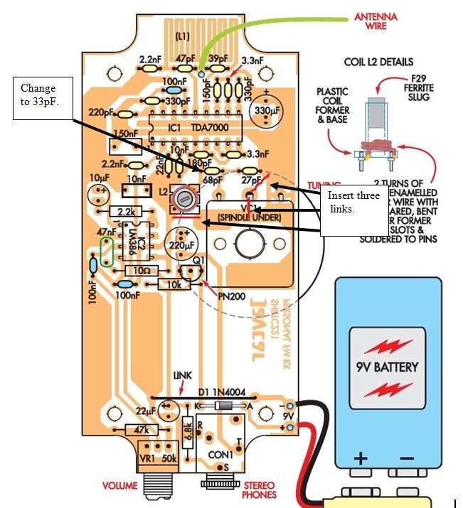
Mods done to the PCB to obtain correct RF performance.
3. Muting.
The TDA7000 muting can be a bit aggressive,
and for a portable receiver with an inferior aerial, my preference is to
disable it. This is simply done by connecting a 10k resistor across the
0.15uF capacitor at pin 1.
4. Parallel Headphones & the
Power Switch.
My intention was to connect the left and
right channels together and modify the switching circuit. To do this entailed
cutting the PCB adjacent to the R (ring) terminal of the socket and connecting
it to the T (tip). Then the S (sleeve) was to be connected to earth. I
tested this, and it worked as expected. The switching is where things became
problematic. My idea was to connect the 6.8k resistor to the now paralleled
tip and ring connections. The circuit would work as before, except when
the phones were unplugged. In this instance, current would now flow through
the 220uF in reverse, since the LM386 output pin was now at earth potential.
The way around this would have been to replace the 220uF with a non-polarised
type. Unfortunately the largest non-polarised capacitor I had that could
fit the PCB was 47uF, which was too low. The cost and inconvenience of
ordering a capacitor just for this killed off that idea.
Mechanical switches were considered, but slide or toggle switches always get bumped into the 'on' position when least expected, discharging the battery. The ideal would have been to use a switch pot for the volume control. None of the small size required were conveniently available, and there is certainly no room for anything larger than the existing potentiometer. Ultimately, it was decided to revert back to the original set up. The anti-phase connection of the headphone drivers was actually tolerable, although not 'correct'.
5. Headphone Lead as Aerial.
No one wants a wire dangling out the back
of a small portable radio. Aerials should be self contained. As it happens,
there is already a wire we can use instead; that being the headphone cable.
The Elektor TDA7000 receiver uses the headphones this way, as do the small
auto-scan TDA7088T receivers, and my 6
transistor super-regenerative receiver.
For the Jaycar receiver, implementation
is quite easy. Two likely looking RF chokes were found and connected between
the T and R connections of the headphone socket, and their respective audio
and earth connections The value is not critical, but about 5 to 25uH would
be typical. The chokes I found were the tiniest toroids I had ever seen,
and they measured about 22uH. Having done this, the headphone lead can
now float at RF above the circuit earth, while the low inductance of the
chokes does not impede the audio signal. The sleeve connection of the headphone
socket was then connected to the aerial input, at the junction of the 39pF
and 47pF capacitors. By default, these capacitors also isolate any DC on
the headphone socket, so the aerial input does not interfere with the switching.
The 6.8k is high enough not to load down the RF signal, so a third choke
is not required for the sleeve connection.
Results are quite good, and no worse than
the dangling 75cm length of wire. A limitation of headphone cable or other
wire aerials for VHF is that they're often not in the ideal position, so
some experimentation is required to obtain best reception. A 75cm telescopic
aerial would be better, but there is definitely no room to include one!
At this point I was happy, and it was
working as a typical TDA7000 receiver of this type should.
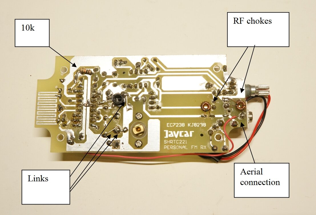
Showing the modifications to the PCB. The 10k disables the squelch.
Two links are used to earth the tuning condenser moving plates to minimise
inductance.
Fitting the Case together.
I had a lot of difficulty getting the
lid on the case because of the battery. Ideally, the PCB would be lower
in the case, but the side of the tuning knob would then be too close to
the other side of the case. The way the PCB is mounted requires four small
spacers so that the tuning condenser knob clears the bottom of the case.
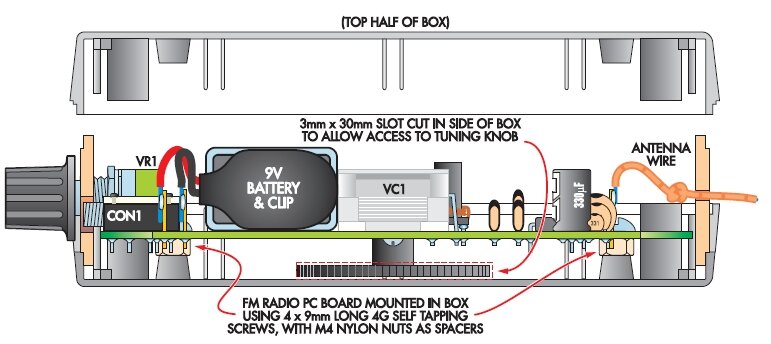
Taken from the book, this shows how the PCB is mounted in the case.
Problem is the height of the battery prevented the top half fitting correctly.
I thought about some other 6 to 9V battery that would fit, but nothing convenient came to mind. Ultimately, I had to cut plastic from the top half of the case with a Dremel. This was messy and time consuming, and care had to be taken not to remove too much. Nevertheless, the required result was achieved.
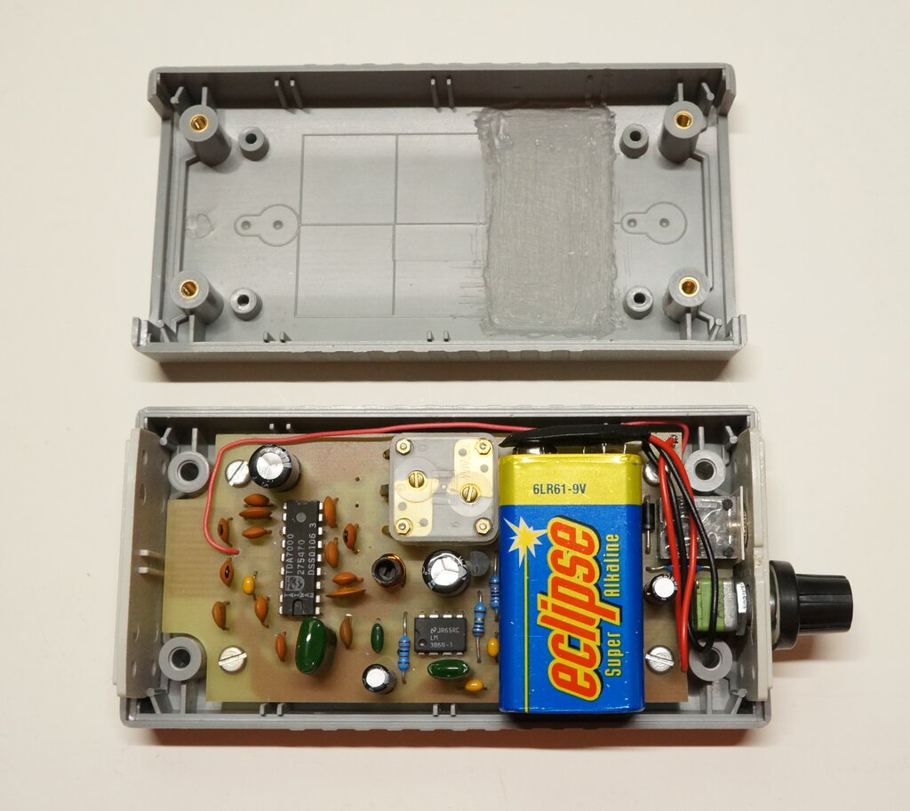
Completed receiver. Note the plastic removed from the lid so the
battery could fit. Red wire connects headphone socket to aerial input.
Before building the other kits, I will select the spacers first so the battery fits, and then shorten the tuning condenser shaft to fit if necessary.
Further Improvement.
The receiver seemed to work quite well
at my location in the Blue Mountains. Being well above sea level, VHF reception
is very good from the Sydney transmitters, about 80km distant. It
still wasn't as good as the Silicon Chip or Mains TDA7000 receivers, and
I put this down to the headphone aerial being less efficient. When I took
the receiver into Sydney, to a location with not so good reception, the
receiver was difficult to use, and received less stations than it should
have. My suspicions of non-optimum performance were confirmed.
I had noted that at the high frequency end of the band, just past 108MHz, that it seemed unstable. There was a rushing noise similar to a super-regenerative receiver with no signal, but more 'ragged' in its sound. This varied with the tuning. Out with the spectrum analyser to examine the local oscillator. And here it was plain to see; a rather ragged shape of the spectrum. Comparing this with one of the Silicon Chip receivers, the difference was clear to see - for it had a clean spectrum, as you would expect. Incidentally, it was quite interesting to see the AFC grab onto the carriers, as I tuned through the band. It is very effective! It was also interesting to see the local oscillator modulated by the audio signal (the Frequency Locked Loop circuit), when it locked onto a station.
Now, what to do about it? I had hoped it
might be a layout or bad earthing problem. While the PCB design is not
exactly like the Philips or Silicon Chip designs, it isn't so far off to
be a problem in itself. Especially after I added the extra links. As I
poked around with a .01uF capacitor at various points, I discovered a clean
L.O. spectrum, if pins 10 or 12 were bypassed. I put this down to the FLL
circuit not being able to modulate the L.O., when the IF signal was bypassed.
I then checked all the capacitor values which were correct. Despite the
ragged L.O. spectrum, once locked onto a signal, there was nothing wrong
with the sound. In fact, a non-technical person, not familiar with what
the TDA7000 is capable of, probably would not think anything was wrong.
I then noticed a brief clean spectrum
when the power was disconnected. Maybe the oscillator was too fierce. Sure
enough, running it off a variable supply did 'fix' the problem. If the
voltage was reduced to a little below 5V, the L.O. became stable. But it
should work perfectly well on 9V!
What about the coil itself? Well, it was
of thinner wire, and wound in the opposite direction of the Silicon Chip
receiver. I noted the Jaycar instructions specify 0.5mm wire, but Silicon
Chip specifies 0.63mm. At least it would eliminate something if I made
the coil as per Silicon Chip.
And that was it! I'm more inclined to
think it was the direction of the winding, and not the wire gauge. I've
encountered this sort of thing before, with the pulse counting and super-regenerative
receivers, where the direction of the magnetic field can add to, or cancel
that of nearby coils.
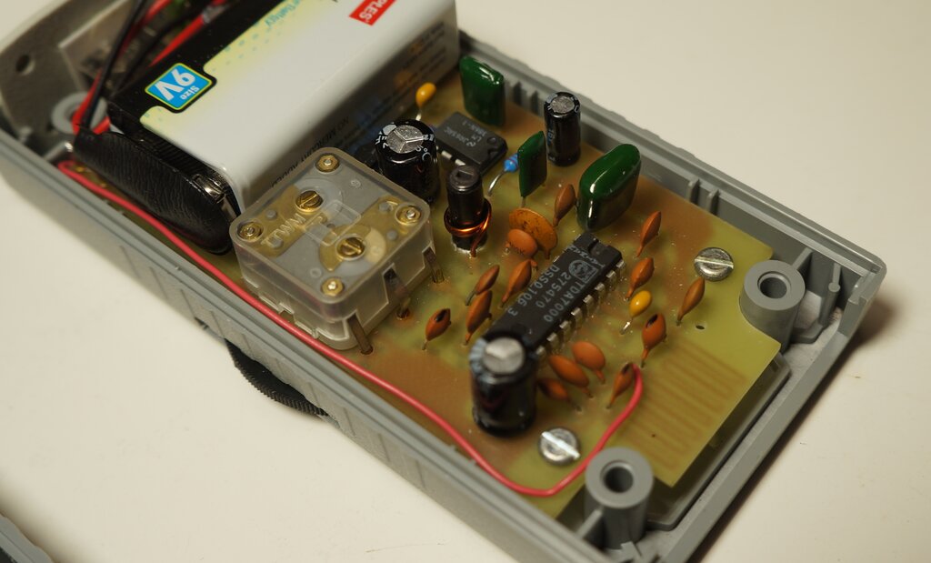
Note direction of the local oscillator coil winding.
Reception was vastly improved. The L.O. spectrum was clean, and the sensitivity noticeably better. Even the headphone aerial was working far better than it was before, with some of the weaker public stations easily receivable. The receiver was now what it should be.

.