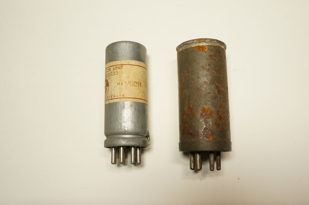
Oak V5211 and Ferrocart PM126 are the most common Australian split reed vibrators.
Oak V5211 and Ferrocart PM126 are the most common Australian split
reed vibrators.
There are two types of split reed vibrator.
The most common is that used in a conventional synchronous circuit, where
the second contact set provides rectification. In this instance, the secondary
contacts open and close slightly before and after the primary contacts.
The other type is the split reed dual
interrupter, also known as the "communications" type in the U.S. This type
does not provide rectification, but instead both sets of contacts operate
in the primary circuit, so as to increase the input power rating. The split
reed allows a novel design, whereby either a 6 or 12V supply can be used
without alteration to the vibrator or transformer.
Synchronous Vibrator Operation.
By using a second set of contacts operating
in synchronism with the primary interrupter contacts, it is possible for
the vibrator to also operate as the rectifier. The main advantage is the
saving of the heater current required by the rectifier valve (typically
600mA). The elimination of the rectifier valve also allows for a more compact
and cooler running power supply. Furthermore, although seldom promoted,
the operating conditions of the vibrator are more favourable.
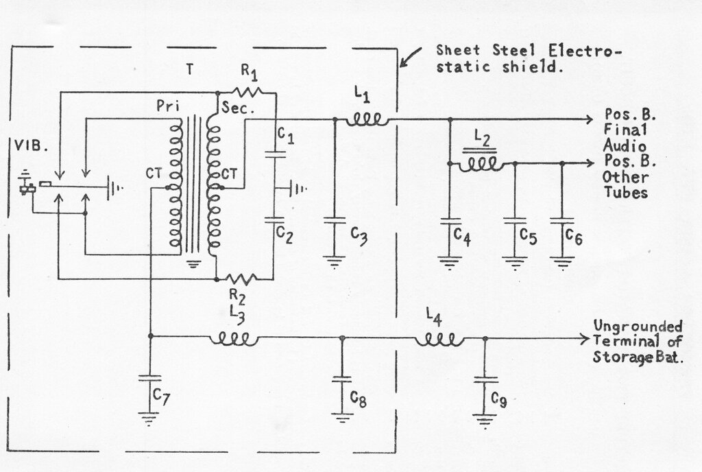
Typical synchronous vibrator circuit, shown with a Ferrocart PM104.
It is assumed that the reader is already
familiar with the non-synchronous vibrator circuit with separate rectifier.
In the synchronous circuit, note that instead of being connected to the
plates of a rectifier valve, the secondary winding is connected to another
set of vibrator contacts.
Looking at the above circuit, the primary
circuit works in the usual way, using the right hand set of contacts. Rectification
is carried out by the left hand (secondary) set. One way to understand
operation is to consider the secondary contacts as diodes, with the cathodes
connected to the secondary winding, and the anodes to earth. The circuit
then becomes a conventional full wave centre tap type, but with the centre
tap being positive with respect to earth. Since the diodes switch in
synchronism with the primary contacts, we can see that output polarity
remains constant.
Negative Bias.
Where indirectly heated valves (AC mains
types) are employed, it is a simple matter to provide bias for each valve
by a cathode resistor. Cathode current causes a voltage to be developed
across this resistor, thus raising the cathode above earth by this voltage.
With the grid returned to earth, it can be seen that the cathode is now
positive with respect to grid. In turn, this means the grid is now negative
with respect to cathode. For sets using this type of valve, the power supply
needs to provide only the heater current, and B+ for the plates and screen
grids.
Directly heated valves (battery types) cannot, in the normal way, obtain bias from cathode resistors, since most of the heater voltage would be lost across such resistors. Instead, a separate bias supply is provided (designated C-). The simplest way to provide this is from a battery. Since no grid current flows, the battery is merely providing an electrostatic charge, and the battery will last for its shelf life. This was once a popular method, and batteries were made especially for the purpose.
Particularly for portable sets, minimising the amount of weight and space taken by batteries is a desirable feature. To this end, the C battery can be eliminated by means of a "back bias" circuit. Here, a resistor is connected in series with the negative side of the B battery to the chassis.
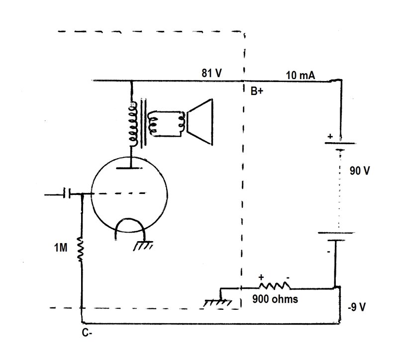
Back bias circuit creates negative voltage from B battery.
If, for example, the B+ current draw is 10mA, and the resistor is 900 ohms, we can see that 9V will be developed across this resistor. The side of the resistor connected to the negative terminal of the B battery will be negative with respect to chassis. Thus, the bias voltage can be taken from this junction. The disadvantage with this scheme is that the bias voltage is subtracted from the B voltage. In this example, with a 90V B battery, the actual B+ voltage would be 81V. In practice, this is a minor disadvantage, and most 'modern' battery sets use the scheme.
In the case of battery valve sets operating
from a 6V accumulator, it is usually possible to use the heater circuit
itself to provide the bias. The valve heaters are connected in series across
the accumulator.
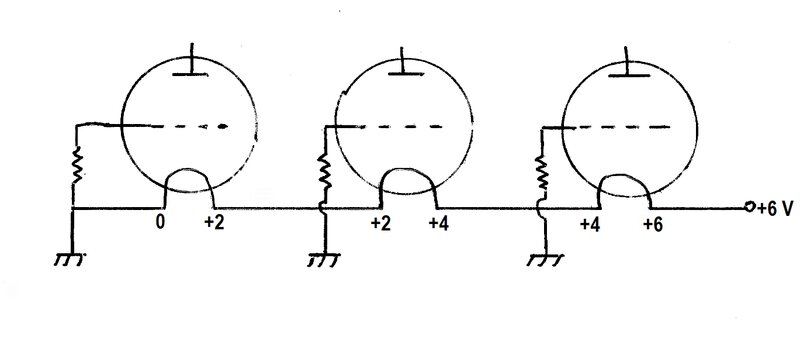
Obtaining bias from the heater circuit (2V heaters).
Typically, battery valves have 1.4V or
2V heaters. So, as long as the heater currents are equal, four 1.4V heaters,
or three 2V heaters can be strung across a 6V accumulator. If the negative
side of the accumulator is earthed to the chassis, it can be seen that
the heater at the 6V end of the string will be this voltage positive above
earth. And, if the grid of this valve is returned to earth, the heater
(cathode) is therefore positive with respect to grid. In turn, the valves
further down the chain will receive less bias, since their heaters are
correspondingly closer to earth. In the example above, the valve closest
to the battery receives -4V bias (referenced to the negative filament terminal).
A limitation of this scheme is that the maximum bias available is no more
than the heater supply voltage present at each valve. In practice, by wiring
the heater string in a certain order, and with the valves typically used,
the scheme works well, and was commonly used.
Since the heaters are also the cathode,
the plate and screen current will also add to the heater current. In series
circuits, this has to be taken into account, and equalising resistors may
be required. The above circuit is to only explain the concept in
its simplest form.
Where a synchronous vibrator is used to
power a battery valve set, a difficulty can arise. Because the reed is
common to both the primary and secondary contacts, and is earthed, it is
not possible to generate any negative voltage by means of a back bias circuit.
If sufficient bias can be obtained from
the heater string, all well and good. If one or more valves requires, say
-7.5V bias, and the accumulator is only 6V, what then? Well, we could simply
use a C battery made of five 1.5V dry cells.
Although quite practical, it gets away
from the idea of only one battery powering the whole set. [If
implementing this idea in the modern day, the preference is to use carbon
zinc cells, since alkaline types are no longer manufactured to be chemically
stable, and often suddenly begin leaking]
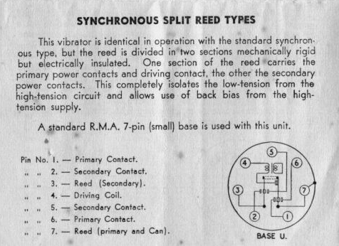
The split reed vibrator solves this problem. The reed is divided in half, with the primary and secondary contacts electrically isolated from each other, but mechanically coupled by an insulator. The negative side of the output is no longer tied to earth, and a back bias circuit can be implemented, to provide any negative voltage required.
Split Reed Synchronous Circuit.
Split reed circuit shown with Ferrocart PM126 vibrator.
Now that we have a separate reed (electrically
speaking) for the secondary circuit, we can see that neither side of the
rectified output has to be tied to earth. Both "Pos. B." and "Neg. B."
in the above circuit are floating above earth.
It becomes a simple matter to generate
negative bias, with a back bias resistor in the usual way.
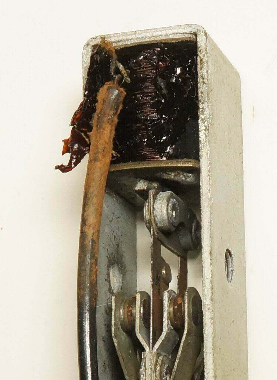
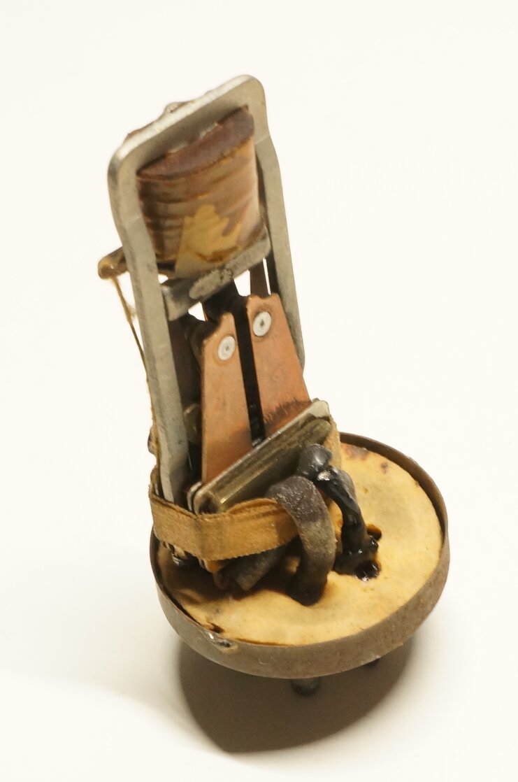
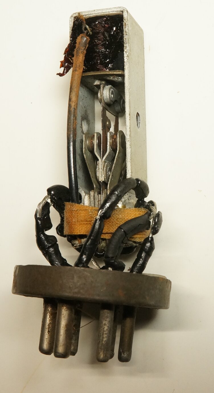
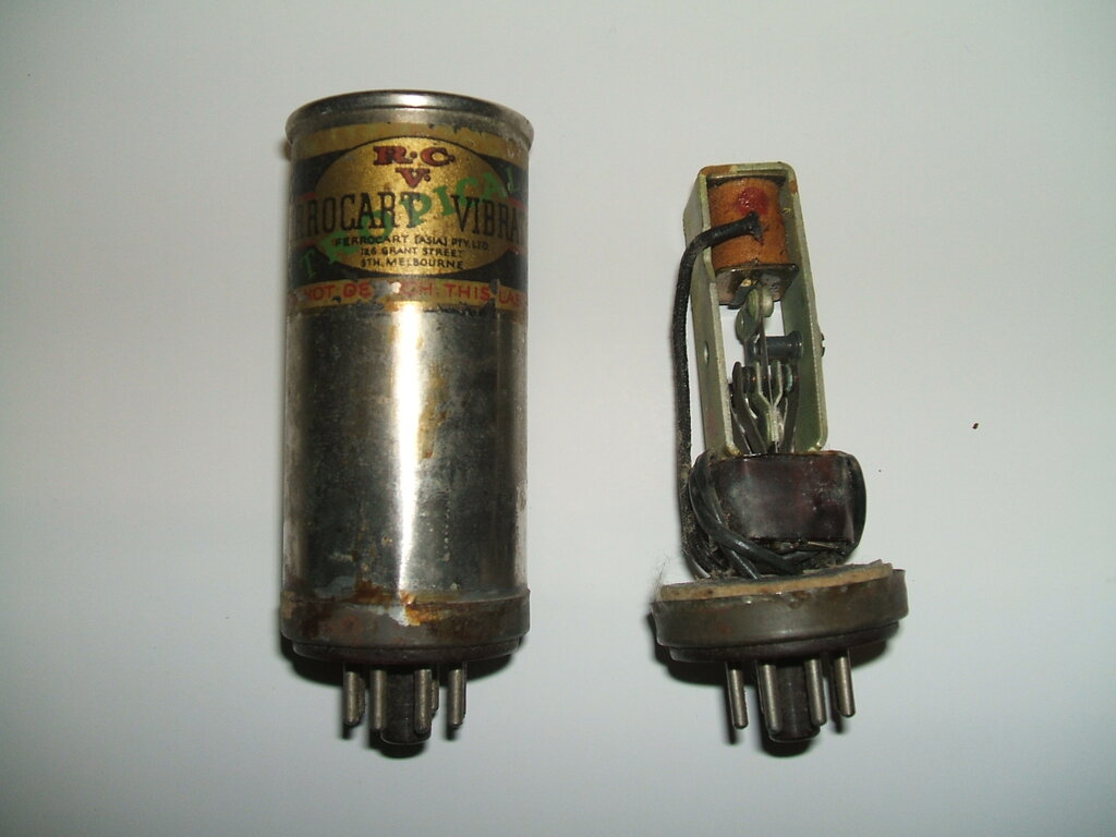
Close up of the split reed construction (Ferrocart PM126). Insulators
are between the reed and weight.
It can be seen in the above photo that
for the most part, the construction is the same as a conventional synchronous
vibrator. Closer examination will reveal the insulating plates between
the reed weight and reed. It is behind here that the reed is split.
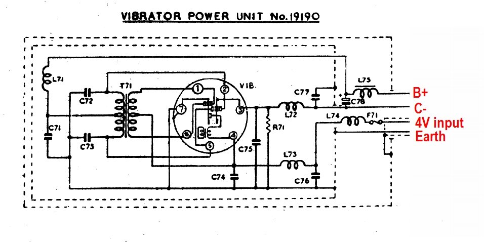
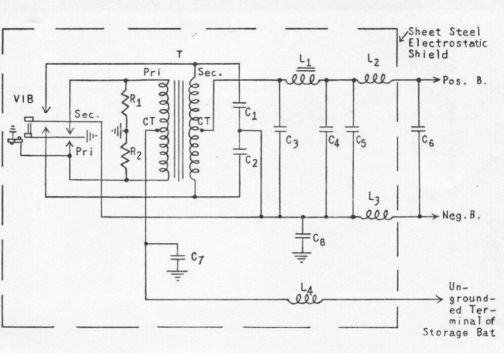
Power supply for AWA 558-TC radio. Vibrator is an Oak V6804.
The above power supply is a commercially
made example made by AWA, which operates a set using 90V battery valves.
Fundamentally, the circuit is the same as the previous theoretical one,
but here we see the method of generating a negative supply.
Note that the secondary reed (pin 3) is
connected to earth via R71. This is the back bias resistor, and negative
voltage is developed in the same way as with a B battery supply. In this
circuit, R71 is 175 ohms. If the B+ current draw is 12mA, the bias developed
will be -2.1V.
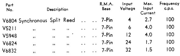
Split Reed Vibrator Types.
Australian made apparatus will usually
use either Oak or Ferrocart types.
Oak:
Oak split reed vibrator data.
| PM126 | 6V | |
| PM420 | 12V | |
| PM529 | 2V | |
| PM530 | 4V | |
| PM562 | 6V | tropical |
| PM357 | 12V | tropical |
| PM957 | 12V | tropical |
Of the two types of split reed Ferrocart types so far examined, an Oak mechanism is used. The PM957 uses the conventional separate drive Oak construction, and is mounted on an octal base. Tropicalised construction is used, which entails the can being completely soldered around the base, and the vibrator can is varnished. It was used in military applications only. The PM126 is the most common of the civilian types, and is mounted on a UX-6 base. It also uses an Oak mechanism, except modified for shunt drive. In the above photos, one can see the threaded hole normally occupied by the drive contact, and that the mating contact is still present on the reed. The Oak mechanisms used in these vibrators are of slightly different appearance to the locally produced AWA product, in that the metal has a duller finish. Quite possibly all or some of the parts were made locally by Radio Corporation, or sourced from the U.S.
Ferrocart PM957.
Conversely, AWA had no problem producing the Oak split reed vibrators in Australia, and they were very popular. One has to wonder if it was really to do with patents. There appears to be virtually no information on the Oak vibrators produced in the U.S., except for what can be determined from Radiart and Mallory cross reference charts. In most instances, type numbers differ between Australian and U.S. types, especially where the Australian types have been locally developed. It is not known if Oak in the U.S. was producing split reed vibrators prior to the Australian patent, and if it was actually the Australian development, that led to Oak producing the split reed communications types for Motorola in the mid 1950's.
Series Connection of Power Supplies.
One model of AWA Carphone power supply
used two 150V split reed vibrator power supplies in series, to provide
150V for receive, and 300V for transmit. This power supply also allowed
for operation from either a negative or positive earthed supply, simply
by swapping the positions of the two vibrators.
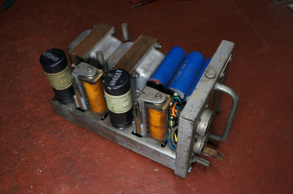
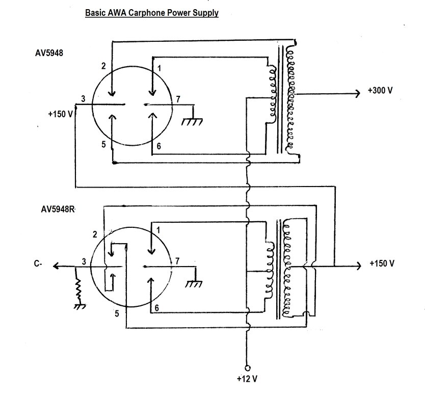
AWA Carphone uses two split reed synchronous vibrator power supplies
in series.
Essential parts of AWA Carphone power supply. Drive coil circuit
not shown.
The power supply uses a type AV5948 and AV5948R vibrator. These have been described here, but briefly, the "A" prefix indicates the vibrator is aged, and is also painted black for improved heat dissipation. Importantly, the "R" suffix indicates that the secondary contact connections are reversed inside the vibrator. The reason for this will soon become apparent. The transformers both produce 150V.
The lower power supply is completely conventional, despite the appearance of the crossed over connections. +12V is fed into the vibrator transformer, and the phasing of the windings is such that +150V is produced at the secondary centre tap. A back bias resistor connected between the secondary reed and earth provides a few volts negative, in the usual way.
Turning now to the upper power supply,
this is again a conventional split reed synchronous circuit. For a moment,
assume the secondary reed (pin 3) is earthed. Output at the transformer
secondary centre tap would be +150V. However, instead of being earthed,
pin 3 is instead connected to +150V. It can be seen therefore, that with
the 'earth' of this power supply now referenced to +150V, that the output
will now be +300V.
As it stands, the circuit could be built
with two split reed vibrators of the same type, and the correct outputs
would be obtained, assuming of course, the transformers were phased correctly.
Why does one vibrator have reversed connections? As shown, the circuit is for a negative earth supply. Now, consider the lower circuit. To use this circuit on a positive earth supply would entail having to reverse the transformer secondary connections; either by desoldering and resoldering wires, or by swapping connections over on a terminal strip. We could avoid all that simply by removing the AV5948R and plugging in an AV5948, since this will reverse the secondary connections relative to the contacts. So, with our positive earth power supply, the output polarity is again correct.
What of the upper power supply? When used on a positive earth input (i.e. -12V), the output of the transformer would then be -150V. However, since it's referenced to the +150V from the lower supply, there would be no output. Again, the transformer secondary connections need to be reversed. And it just so happens we have the AV5948R left over from the lower circuit to do just this.
The advantage of this scheme is that converting from negative to positive earth merely requires swapping the vibrators. No tools are needed. Incidentally, this version of the power supply is one of three types known. Another version uses two V6606 dual interrupter vibrators, with rectification performed by selenium rectifiers. Its feature was operation from 6 or 12V supplies without having to change the vibrators or transformers. Later versions of valve Carphones used a transistorised power supply.
Polarity Reversing DPDT Switch.
Since the two sets of contacts are isolated
from each other, it's possible to connect a split reed vibrator as a DPDT
switch. This eliminates the need for a centre tapped primary. One such
circuit which used this technique was that of the Bland
Radio shaver inverter.
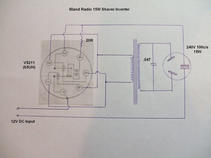
Bland Radio inverter uses split reed vibrator as a DPDT switch.
An extension of this idea is to operate a 6V vibrator transformer on 12V. In this configuration, a split reed vibrator is connected so it works as a DPDT reversing switch, applying +12V then -12V to the full primary. In effect, the primary receives the same peak to peak voltage that it would on 6V when used in the conventional way. The centre tap is no longer used; only the outer primary connections. The regulation and efficiency is as per original, and the transformer needs no modification.

It's a useful idea to keep in mind if there is a need to convert a 6V power supply to 12V. The vibrator and socket will have to be changed in most instances, and if the set previously used synchronous rectification, a separate rectifier will have to be installed. Only separate drive vibrators are suitable for this application. Of course, a drive coil dropping resistor is required if using a 6V vibrator. Since the contacts are not providing rectification, this technique is also suitable for communications vibrators.
Negative Bias from a Non Split Reed
Vibrator.
As we've seen, the main purpose of a split
reed vibrator is in synchronous circuits where a negative voltage needs
to be produced. What if you're building a new circuit, or restoring a set
with a missing vibrator, and can't get a split reed type?
One option is to forego the synchronous
rectification, and use silicon diodes such as 1N4007's, using a back bias
circuit. The replacement vibrator can then be a non synchronous type, or
a synchronous type with contacts paralleled.
If a synchronous vibrator is available,
synchronous rectification can be retained, and the negative supply generated
by an additional circuit.
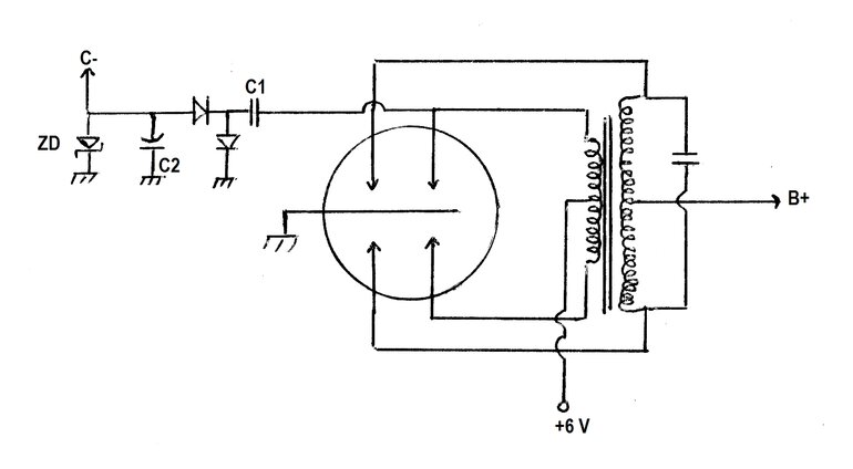
Obtaining bias from a synchronous circuit.
In this circuit, negative voltage is obtained
by rectifying the AC developed across the transformer primary. It isn't
as simple as just connecting a diode from the primary, however. Since the
centre tap is always +6V above earth, this means that the outer connections
of the primary also have a DC component of +6V above earth. When one primary
contact closes, the other half of the primary produces -6V, with respect
to the centre tap. Simply connecting a diode to this point to provide a
negative voltage won't work, since +6V and -6V = 0.
We need to isolate the DC component, which
is the purpose of C1. Readers may recognise C1, C2, and the diodes, as
being that of a half wave voltage doubler circuit. And so it is, taking
the 6V p-p from one side of the primary and converting it to -12V.
The maximum negative voltage that can be provided is thus twice that of the input supply voltage. In a practical circuit, various losses reduce this slightly. A zener diode provides a degree of regulation. It's not essential to include this, but random narrow spikes on the vibrator waveform will cause the voltage to fluctuate in the upward direction, especially when the circuit is lightly loaded, or not loaded at all. In instances where the required bias voltage is not the same as that of a preferred value zener, a higher voltage zener can be used, and the bias taken from a voltage divider.
In practice, it was found best to keep the zener to 10V or less. The lower the zener voltage, the better the regulation. A series resistor is not necessary, since the reactance of C1 limits the zener current. The values of C1 and C2 are not critical. Normally, a bias circuit draws no current, or is of very high resistance (e.g. 1M), so these capacitors do not need to be of high value. In the experiments performed, C1 was tested with 0.1uF and 0.47uF. C2 was a 10uF electrolytic, and the zener was 7.5V. Even with 500k loading the voltage remained at -7.5V. There was little difference between the 0.1uF and 0.47uF capacitors used for C1. The main effect is with the smaller capacitor, C2 takes longer to charge.
In this regard, when the bias is feeding
directly heated battery valves, the voltage needs to reach maximum very
quickly, before the valves warm up. The above capacitor values were satisfactory.
Another practical consideration is that the added components could radiate
interference, so some thought to their location and layout will need to
be given.
It was not tested, but it should be possible
to obtain greater than twice the battery voltage, by adding another stage
to the voltage multiplier in the usual way.