Made in 1964, this set came to me from
another HRSA member for repair. The fault was considerably reduced height,
and replacing various electrolytic capacitors, and the vertical output
transistor had not fixed it.
The curious thing about this set was how
it got here. A few Japanese sets were imported into Australia in the 1960's
and sold on a small scale. These sets were sometimes built for Australian
standards, but were often simply models intended for the West European
market.
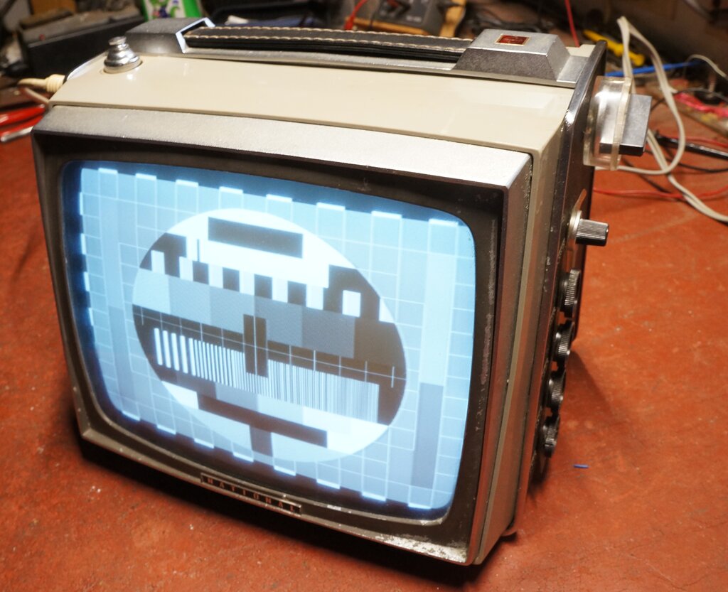
Set operating after repairing three different faults.
The systems are the same as far as operating on system B; i.e. 625 lines, 50 fields, 5.5Mc/s sound IF, negative modulation, and FM sound. The main difference is the European tuner does not cover Australian channels 3,4,5, and 5A. The mains voltage is usually considered 'close enough', although some 220V sets are running close to the limit on the Australian 240V mains. Some were modified for the slightly higher voltage, and some were not.
However, this model of set was not listed
in the Australian JR Television Service Manuals, so I had first assumed
it been brought in as a duty free purchase (as sets sometimes were), or
by a European immigrant. Even more puzzling was a dearth of information
on the internet. In fact, the only reference appeared to be of West German
origin, with an advertisement from 1964, and a partial description in an
electronics magazine.
Then, it turned out that a complete set
of instructions, and a circuit diagram had come with the set. Apparently,
these sets had been sold in Australia by the Melbourne radio dealer, Collins
Radio. It must have been a small quantity for them not to find their way
into the JR manuals.
National set up local production in Australia
in 1969, with a factory in Penrith, west of Sydney, and of course the sets
produced were then fully compliant with Australian operating conditions.
A look at the circuit diagram showed it to be of conventional 1960's Japanese transistor design, and I did not anticipate any great difficulty in finding the fault. One of the interesting things is the presence of a few early NPN silicon transistors. Many sets of this era were exclusively using germanium PNP types. It seems that Sony were an early developer of silicon NPN transistors, and some of these were being used by National.
Incidentally, for the benefit of U.S. readers, National was branded as Panasonic in the U.S. to avoid confusion with the already extant local brand of the same name. Elsewhere in the world, the brand was National Panasonic, or simply National. The National brand was dropped in the mid 1990's, when it became Panasonic world wide.
The Design.
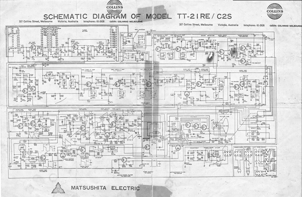
Download the high res version in the link below.
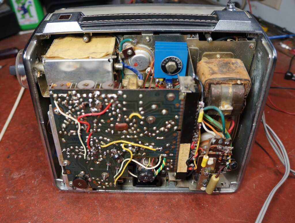
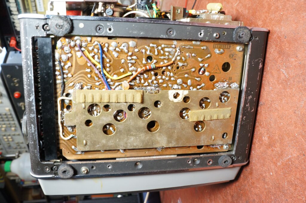
The line output transistor is at top centre, with the selenium rectifier
to its right. Further to the right is the power transformer, and underneath
that is the line output transformer and EHT rectifiers.
The front incorporates a plastic safety
glass for the CRT, since it has no inherent implosion protection. Under
the set is a steel ventilated panel.
Most the circuitry is on two swing out
PCB's fitted with edge connectors. At the bottom of the set is the front
end, audio, and video circuitry. At the back is the deflection and active
filter circuitry. A metal chassis between the two cabinet sides holds the
tuner, power transformer, rectifier, filter capacitors, line output circuit,
and active filter transistor. The speaker is mounted on the right hand
cabinet side.
Power Supply.
The power supply uses a C-core transformer
and selenium rectifier. It is not regulated. There is a dynamic/active
filter however, (T62 and T44), which was commonly used in sets of this
era. It is an odd thing that so many solid state sets did not have voltage
regulation in the early days, when an active filter is so easily adapted
for it. Possibly it was a legacy of the valve era where regulation was
not important. Even as late as 1978, at least one set, the JVC 3040CQ,
still didn't have regulation.
Two mains tappings on the transformer are
provided, for 220V and 230V. There is no 240V tapping. This brings up the
question of where the set was intended to be sold. 220V would have covered
the European countries where the set could be used, so why 230V? The only
country using 230V that I can think of was NZ, and it's quite possible
the set was sold there, since the TV standards are the same. It could also
be that Collins Radio specified to National the requirement for 230V, since
this was the standard voltage in Victoria until the early 1960's. And,
as I discovered later on, it does seem as though the set sold here had
been spec'd to Australian conditions, since it can receive our 'unique'
channels (3,4,5,5A). Since the original channel knob was missing, there
is no way of knowing how it was labelled as to channel numbers.
Something curious, if the circuit diagram
is to be believed, is that the mains bypass capacitors are not actually
across the full mains when the 230V tapping is selected. They remain permanently
across the 220V tapping, and would be less effective connected thus. It's
as if the 230V tapping was something of a later afterthought. Incidentally,
if the set's power supply was regulated, the need for the extra transformer
tapping would have been eliminated.
The set can also work from a battery, which is of a rechargeable alkaline type, consisting of two 6 volt units. This is recharged using the transformer and rectifier in the set. Again, this was a common arrangement in 1960's solid state portables. It is doubtful that most owners would have actually maintained the batteries, and they would have had a short life. It appears that the battery charge meter is only connected across one of the batteries.
It's a cumbersome arrangement, but such was the technology of the
time if you wanted complete portability.
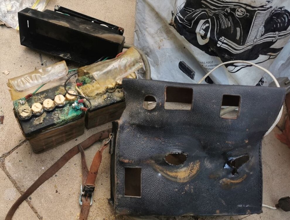
Battery as found. Constant attention and maintenance is required
to avoid this. In the modern day, lithium batteries have eliminated this
problem.
Battery case after being cleaned up.
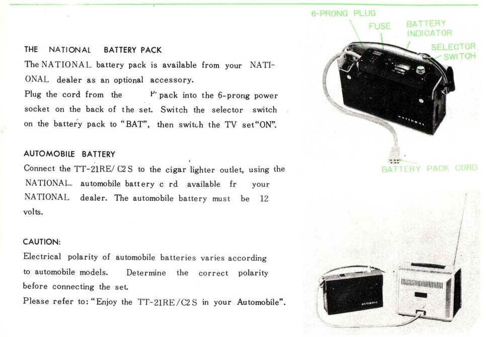
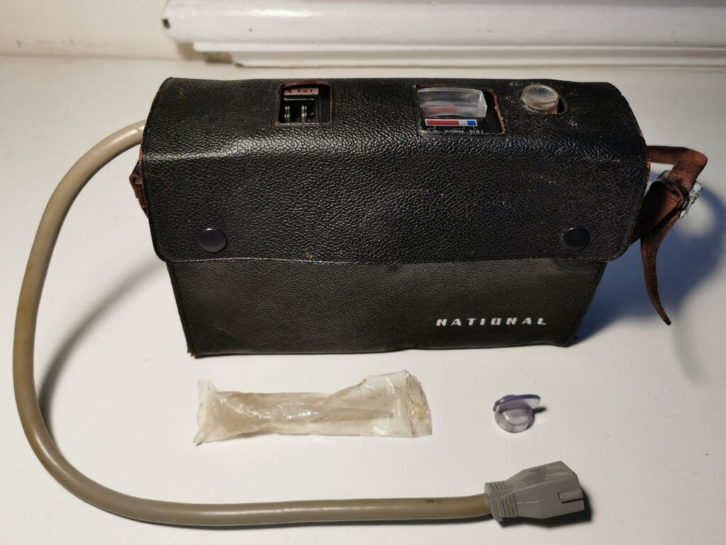
Also provided is a car adaptor. In the circuit diagram, this is nothing more than a cable with a cigarette lighter plug and a reverse polarity protection diode. What came with the set is a bit more advanced, being a small box containing a regulator circuit. This is a good thing, since feeding the voltage from a car electrical system directly into the set with no regulator could be detrimental to the picture tube heater, among other things.
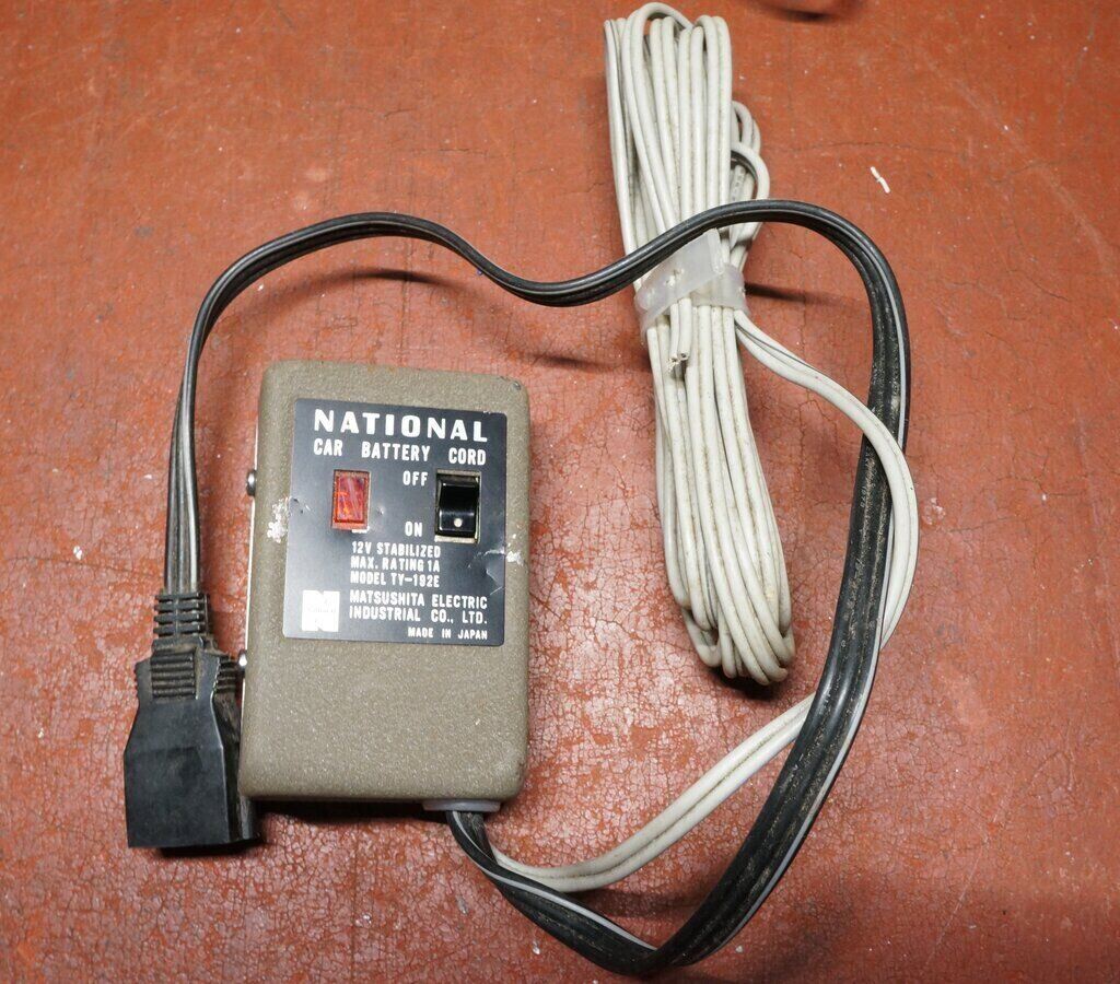
Car adaptor contains a voltage regulator.
Like other sets of this type, a proprietary multi pin plug of moulded construction connects the set to the various power sources. Moulded plugs often fail where the cable enters the plug body, and so it had for the mains cable with this set. Someone had cut the plug open to repair it and glued it back together. I did not investigate this closer, feeling it best to leave it alone since it was working. I wish the set makers would use rewirable plugs in these situations.
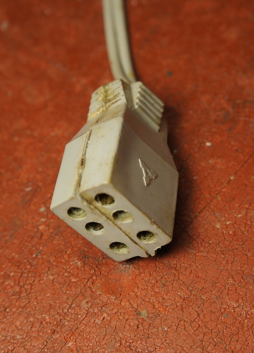
The 6 pin power plug had been repaired before.
Somewhat surprisingly, I discovered the 6 pin plug fitted a Russian made Tento 402D-1 television. That is not to say the plugs are wired internally the same, although it does appear the mains input connections are at least. In any case, multi pin power plugs from other sets should not be used without checking this first.
Tuner.
Only a VHF tuner is provided, although
mention is made in the manual of being able to plug in a UHF tuner - presumably
a converter fed into the aerial socket. The UHF converter is not shown
in the instructions, or even as being available as one of the accessories.
The tuner is of the incremental type with
three transistors. A telescopic aerial is of course provided, along with
external aerial inputs; one being a 3.5mm socket. The other is a two pin
socket which also provides supply for the UHF converter. The circuit also
shows the availability of a balun box with attenuators, for connection
to an outdoor aerial.
A peculiar thing is the instruction manual
specifies the tuner as being of U.S. standards, with their channels 2-12.
How this is possible, when U.S. channels are 6Mc/s wide, against 7Mc/s
of European channels, leaves something to the imagination. European channels
are also numbered 2-12, so it could just be a mistake.
And this brings up another question; was
there a 120V version of this set sold under the Panasonic brand in the
U.S.? Aside from the alignment of the video and sound IF, and the differences
in channels and mains voltage, it would have been a simple matter to create
a U.S. model.
In fact, it could well be that what we're
seeing here is actually a European version of a U.S/Japanese model. Generally,
since the Japanese and U.S. TV systems are the same, except for channel
frequencies, and the 20V difference in mains voltage, most Japanese sets
were made for the U.S. market first, before being adapted to European conditions.
IF Amplifiers & Audio.
The video IF stage is quite conventional
using three transistors (T11, T12, T13?), followed by a detector diode
(D11). The 5.5Mc/s sound IF is taken from the first video amplifier (T14),
and fed into a two stage sound IF amplifier (T21, T22), before being detected
by a ratio detector (D21, D12). The audio amplifier is a very typical design
using a driver transistor (T23) and a two transistor class B output stage
(T24, T25). Two earphone sockets are provided; one which disconnects the
speaker, and one which doesn't.
Video Stages.
These are described in more detail further
down since one of the faults was related to this section. Briefly, the
detector (D11), feeds an emitter follower (T14) which in turn feeds the
contrast control. This is connected like a volume control, rather than
the more common method of a variable emitter bypass. From here, the video
signal feeds the output stage, which is a cascode arrangement using T15
and T16. As is typical with Japanese and U.S. designed sets of the era,
the video is AC coupled to the CRT. While the true black level is lost,
it does make the contrast and brightness controls easier to adjust, in
that they don't interact with each other. Similarly, brightness of the
picture is not dependent on signal strength. In short, it makes for less
critical operation. The CRT is of 90 degree deflection.
AGC.
This is of the gated type, since the control
transistor (T18) is fed from the line output transformer. Video is fed
into the base of this transistor, and the collector is fed with line pulses.
Therefore, the emitter voltage will only be present during the line sync
period, and thus represent the true signal strength.
Sync Separator.
This circuit consists of three transistors,
T17, T30 and T31. T17 is the sync separator, T18 is the sync amplifier,
and T31 is the phase splitter for the line AFC, which is described further
on.
Vertical Oscillator & Output.
Also very typical of Japanese sets of
the era, a one transistor blocking oscillator (T32) feeds a driver (T33),
then a single ended choke coupled output stage using T34. Waveform correction
feedback is taken from a low value resistor in series with the yoke earth
return, and fed into the driver stage. A thermistor (VM401) compensates
for temperature variation, which would otherwise show up as change in height
as the set warmed up.
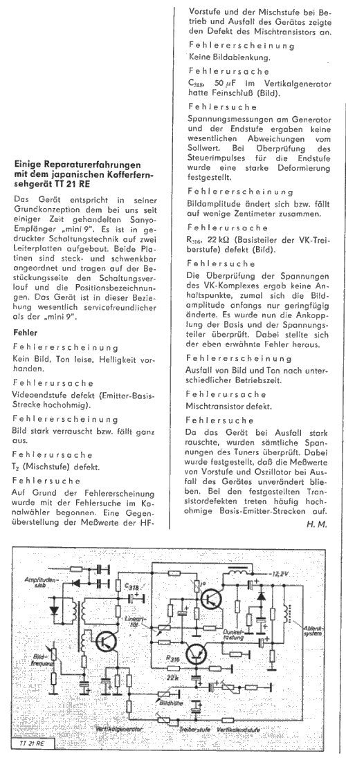
From a West German magazine, this gives an explanation of how the
vertical deflection stage operates.
Horizontal Oscillator & Output.
A one transistor blocking oscillator (T41)
feeds a buffer stage (T42), which interestingly is an NPN silicon type.
This transistor had been replaced sometime in the past. From here, the
signal is amplified by a further driver stage (T43) before finally reaching
the output transistor itself (T61). This is a Sony NPN silicon type 2SC41.
The damper diode is a germanium type MA102. Valve rectifiers are used to
provide the EHT. Three 5642 wire ended valves are connected as a voltage
doubler. Again, this was common design at the time. In fact, 'solid state'
portables retained valve EHT rectifiers until the late 1960's, when selenium
types took over. The horizontal yoke winding is fed from the line output
transistor collector via a large paper capacitor of 6.5uF (C610). Apart
from isolating the DC component, it also provides S-correction. It is worth
noting that in the late 1960's, early 70's, some set makers were using
what appears to be a polypropylene type here, made by Shizuki. It is a
common cause of line deflection failure.
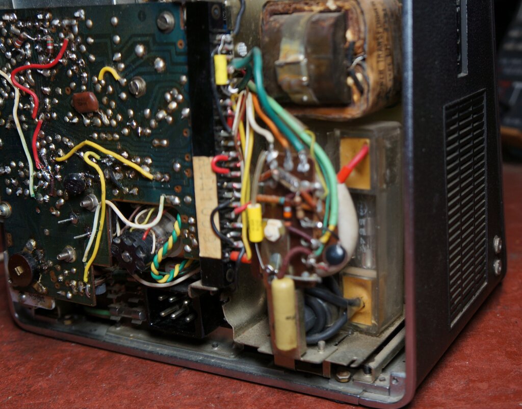
One of the 5642 EHT rectifiers is visible in the clear perspex enclosure
at bottom right.
1) Vertical Deflection.
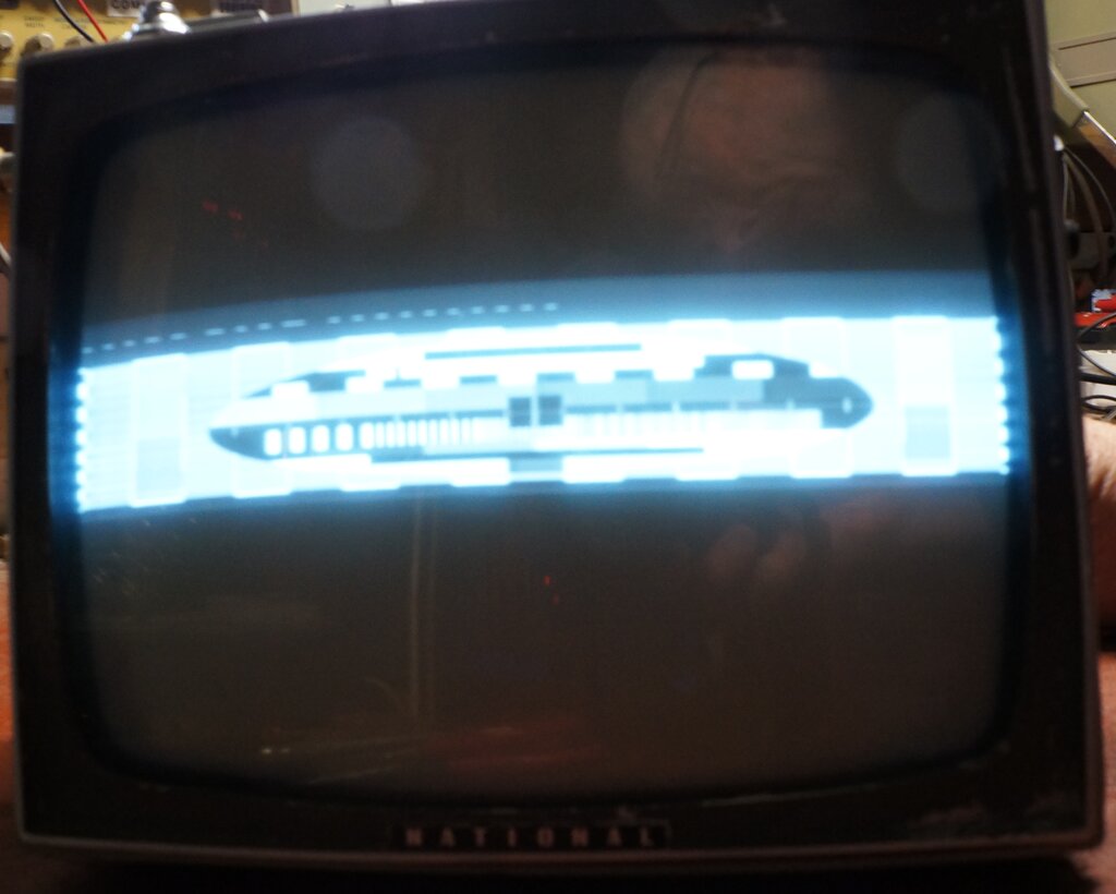
Insufficient vertical deflection.
Lack of vertical deflection is usually a straightforward fault to deal with, but with this set most of the difficulty was identifying the component locations. The component designations on the PCB were all hand written for the initial screen printing, and in many instances difficult to read. Some had worn away and were illegible. To make things more difficult, the PCB is not translucent, so shining a light through it does not help in locating the connections on the track side.
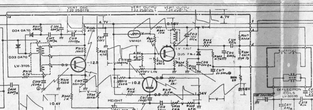
Vertical oscillator and output circuit.
The vertical circuit has three transistors.
One is the blocking oscillator (T32), the second is a driver (T33), and
the third is the output (T34). First thing to measure was the collector
of the output transistor, T34. The peak to peak voltage was very low at
only a few volts. This is at odds with the 12.5V supply rail. Curiously,
the circuit diagram shows it should be 4.7Vp-p, which was also at odds
with other sets using a similar circuit. Something more like 15Vp-p is
what I was expecting. Nevertheless, I accepted the yoke might have been
of different design.
The blocking oscillator waveform was of
correct amplitude; in fact slightly more than shown on the circuit, with
a little over 2Vp-p present at T32's emitter. This wasn't the problem area.
Seeing as the output transistor had been replaced by the new owner, I was
inclined to think the driver stage was the fault.
But first, some other tests. The yoke coupling capacitor, C313 (500uF), can be a frequent cause of the problem because of the continuous high current through it. As far as I could tell, there was minimum loss across it, as well as the 2 ohm current feedback resistor (R336?), in series with the yoke earth return. So, the next step was to find out just what voltage we did need across the yoke to get full deflection. I simply connected a function generator directly to the yoke, and this immediately proved my assumption of the specified 4.7Vp-p being too low. Something like 15Vp-p gave full deflection. The scan under these conditions was far from linear, since the function generator cannot provide the proper waveform, but the point was proven.
Next step was to test the driver transistor. This is a standard germanium audio type. Placing it in the component tester showed it to be PNP, but there was no base to emitter voltage, and no gain. Replacing it with an AC128 restored full deflection, and only a very minor adjustment of the height and linearity controls was required to provide an excellent vertical scan. Measuring the output transistor collector voltage showed we now had about 47Vp-p. Obviously, the decimal point was an error.
2) Bent Verticals.
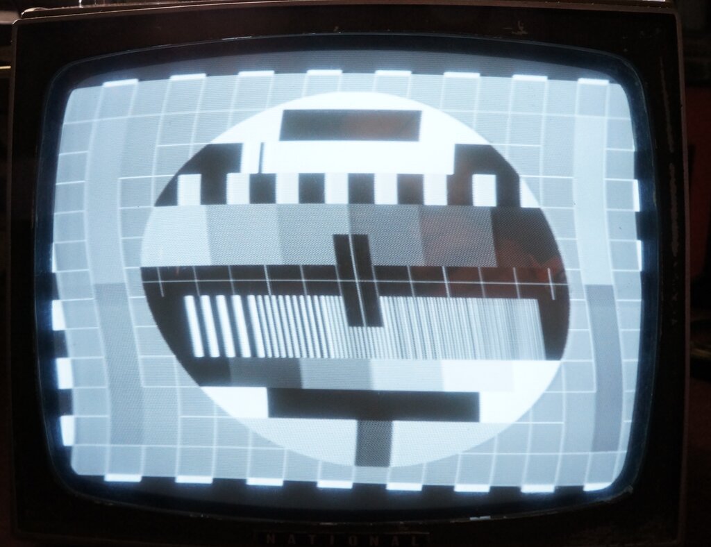
Bent verticals indicate faulty supply filtering, or in this case
the horizontal AFC circuit.
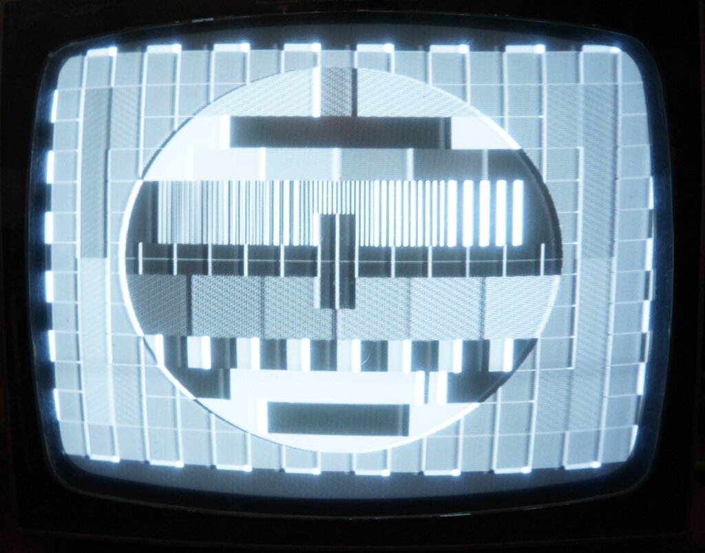
With a Philips PM5544 test pattern fed into the set, it was obvious more work was required. There was a severe vertical bend in the picture. It looked a lot like when the power supply smoothing is defective, and there is mains hum on the supply rail. However, two things indicated it wouldn't be this. Firstly, in tracking down the vertical fault, a CRO on the supply rail showed it was hum free and of correct voltage. Secondly, if it was mains hum, the bend would move up or down the picture, as the mains frequency drifted relative to the field rate of the video source, which in this case is crystal locked.
The next thing was to find out if this
bend was coming from the sync pulses being corrupted, or if it was some
defect in the horizontal oscillator. Conveniently, it's a simple matter
to disable the sync in this set simply by disconnecting the sync wire from
the video board.
Floating the picture by careful adjustment
of the horizontal hold control showed perfectly straight verticals. So,
it was a sync problem.
Looking at the sync pulse waveform showed
everything looked normal here, and that left the AFC circuit.
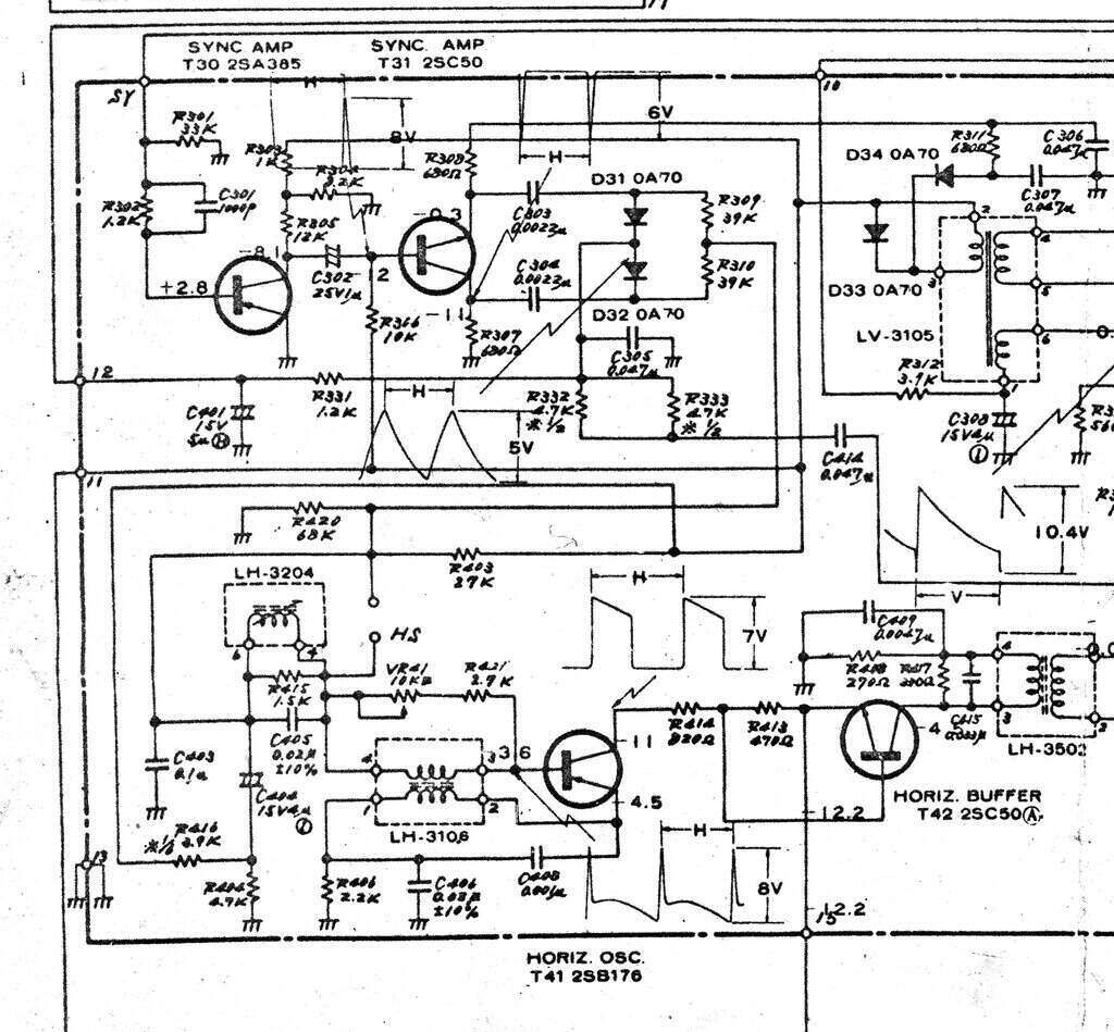
Horizontal AFC and oscillator circuit.
A possible (and likely) fault would be the AFC filter circuit, seeing as there's a 4uF electrolytic (C404), which was original. Alas, it tested better than new on the ESR meter. Someone had been working in this area before, and I noted that T42 had been replaced.
Horizontal AFC.
So, what's this AFC all about? The horizontal
oscillator could be triggered directly by the horizontal sync pulses and
we would get a locked picture. However, in less than ideal conditions,
due to noise or electrical interference, the sync pulses might be corrupted
or might be noisy themselves. This would show up in the picture as ragged
verticals, or in extreme cases, picture tearing. To overcome this, a phase
locked loop circuit is used so that the horizontal oscillator never sees
noisy sync pulses. The sync pulses are compared to the horizontal oscillator
frequency, and a DC correction voltage is produced, which controls the
speed of the horizontal oscillator. If the oscillator runs too fast, the
correction voltage is reduced to slow down the oscillator. Conversely,
if the oscillator runs too slow, the correction voltage is increased. The
important point is this DC correction voltage is fed through a time constant
circuit which is long enough to cover several lines of the picture.
If a sync pulse is missing or noisy on
one or two lines, the DC voltage will not change markedly. Similarly, if
noise gets through the sync separator, the noise pulse will be fighting
against the correction voltage produced by many more good sync pulses.
Essentially, the sync pulses are averaged
over time which improves noise immunity.
What about the vertical circuit? Why does
it not have AFC? Well, to start with one or two 'luxury' sets did have
it, but they are the exception. It comes down to the fact that the vertical
frequency being only 50c/s means that the sync filtering is naturally of
a much longer time constant, and most noise is filtered out by default.
The AFC circuit in this set is very standard.
Sync pulses of inverted, and non inverted polarity, are produced by T31,
which acts as a phase splitter.. These feed the diode discriminator (D31
and D32). At the junction of the two diodes is fed a sawtooth wave from
the line output transformer. Thus, the sawtooth is locked to the horizontal
oscillator.
In simple terms, the conduction of each
diode depends on at what point the sync pulse arrives relative to the sawtooth.
If the sync pulse arrives when the sawtooth is at maximum voltage, then
the diode will conduct more than if it arrives when the sawtooth is at
minimum.
Because there are two diodes; each of
opposing polarity, when the output is summed together, by R309 and R310,
the output voltage will be positive or negative depending how advanced
or retarded the sync pulses are with respect to the line oscillator. There
will be zero volts when the line oscillator is the same frequency as the
sync pulses.
C403 (0.1uF) filters out the sawtooth
and sync pulses so there is just DC to control the oscillator frequency.
However, there is another filter capacitor, of much higher value; in this
case 4uF (C404). This is the capacitor which determines the time constant
of the phase locked loop. The longer the time constant, the longer the
oscillator will stay on frequency with corrupted sync pulses. The time
constant can't be too long however, since that would lengthen the time
the circuit takes to lock. It is therefore a compromise.
Merely connecting a high value filter capacitor
in this manner introduces a problem of the correction voltage overshooting.
The circuit generates a large error voltage to try to lock in as quick
as possible, but because of the time constant, the error voltage will overshoot
after the circuit locks, and it goes off frequency. So, the circuit corrects
itself again, this time with an opposing error voltage and the same thing
happens. What is needed is a critical damping circuit so the error voltage
comes up to the required amount without overshooting.
To achieve this, a resistor is connected
in series with the time constant capacitor. In this set, it is R404 (4.7k)
in parallel with R416 (3.9k).
Finding the Fault.
Touching a 4.7uF capacitor across C404
didn't achieve much except for changing the amount of bend slightly. A
curious aspect of the design is that the damping resistor circuit introduces
a positive voltage at the earthy end of C404. It is not clear why R416
is needed. The odd thing was, when I touched the 4.7uF across R404 it did
nothing, yet directly across C404, the bend changed.
Suitably puzzled, I measured the voltage
at the junction of R416 and R404 and found nothing. With the values of
R416 and R404 across a 12.5V supply, there should be about 6.6V. In fact,
a short circuit was measured across R404. Looking closer, it seemed that
in the past R404 had been replaced, but instead of being installed on the
component side of the PCB, it has simply been soldered on the track side
(lazy serviceman). There was an ever slight solder bridge from the active
end of the resistor to an adjacent earthed pad.
I moved R404 to its correct location,
removed the short, and we had perfectly straight verticals!
One has to wonder how long the set had
been like this. Did the previous owner just put up with the bent verticals?
3) Video Frequency Response.
With now excellent picture geometry, there
was one more thing. The edges of white to black transitions were over emphasised
with a sudden and short increase in brightness. This shows the frequency
response of the video system is over emphasised at the high frequency end.
Excessive high frequency response gives this effect at the edges
of objects in the image. Note that this and the previous photo were taken
after the set was repaired, and the faults recreated - hence the seemingly
wrong order of the bent verticals but with correct video response.
The video board is under the set, and very
difficult to work on. It cannot be hinged out very far while still having
it plugged into the edge connector. A look over the board showed much work
had been done. Removing the main shield (it had obviously been removed
before), showed that work had been done on the video IF amplifiers. In
particular, one IF transistor had been replaced, and it looked like another
had been removed for testing. The track damage indicated poor soldering
technique; most probably with an excessively hot iron.
In fact the tracks around the replaced
transistor were non existent, so the transistor wires were simply bent
over and attached to the nearest intact part of the tracks. I really hoped
the frequency response problem wasn't due to a defect in the IF amplifiers,
or someone's improper servicing thereof.
Front end board is under the set.
Video Amplifier.
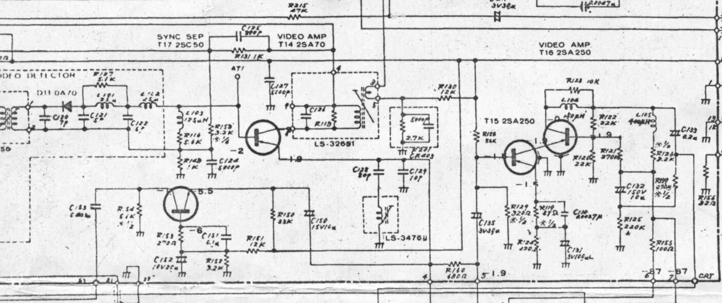
Video amplifier circuit.
Operation of the video amplifier is straightforward
and typical of transistor sets of this era. The video IF is detected by
D11, filtered to remove the IF (38.9Mc/s), and then fed to an emitter follower,
T14. In the collector circuit is a 5.5Mc/s transformer used to extract
the sound IF.
The emitter follower is required because
of the low impedance input of the video output transistors, T15 and T16.
From the emitter of T14, the video signal passes into T15 via R160 and
the contrast control (not shown). T15 and T16 forms a cascode amplifier.
T15 works as a normal grounded emitter amplifier, and T16 works as a grounded
base amplifier. Doing it this way obtains the gain of two transistors,
but with only one phase reversal instead of two. The CRT cathode connects
to the collector of T16 via C133 (0.2uF), and the peaking circuit consisting
of L104 and its associated 10k damping resistor.
Since we had a frequency response problem,
the capacitors were the first thing to suspect. The fault could be anywhere
from the detector diode to the CRT cathode. Since high frequency response
was excessive, an open capacitor would be likely.
First thing to do was just look at the
video waveform on the CRO. And here we could see we were on the right track.
With the CRO connected to the CRT terminal, some improvement was evident.
Changing to a 1X probe introduced more capacitance, and the fault was almost
gone. So, if worst came to the worst, I could do a bodge and simply add
an appropriate amount of capacitance to the output of the video amplifier.
C130 (0.0027uF) partially bypasses the
emitter resistor of T15, and provides some high frequency boost to compensate
for the various stray capacitances in the video amplifier. C131 (100uF)
provides the low frequency bypassing of the emitter circuit. This area
would be the first point of call, given the significance it plays in setting
the video response. Whilst probing around here, the video gain suddenly
increased quite markedly, and at the same time the fault was gone. Something
was touch sensitive! It turned out that C131 had never been properly soldered.
Its leads and the tracks were tinned, but there was not a proper joint.
Again, how long had the set been operating like this?
Anyway, a proper soldering job fixed it.
What had been happening is that with C131 out of circuit is there was only
high frequency gain due to C130. Also, the gain of the stage as a whole
had been reduced since C131 covers both low and high frequencies. Hence,
the increase in contrast once it was reconnected.
The contrast control had plenty of adjustment
even with C131 out of circuit, so no one would have been suspicious. In
fact, now with C131 reconnected, the contrast was slightly excessive even
with the control at minimum, so the AGC had to be backed off slightly.
Given that I found the AGC preset to be almost at one end of its adjustment,
I suspect someone had been here before too - possibly adjusting it to compensate
for the loss of video gain.
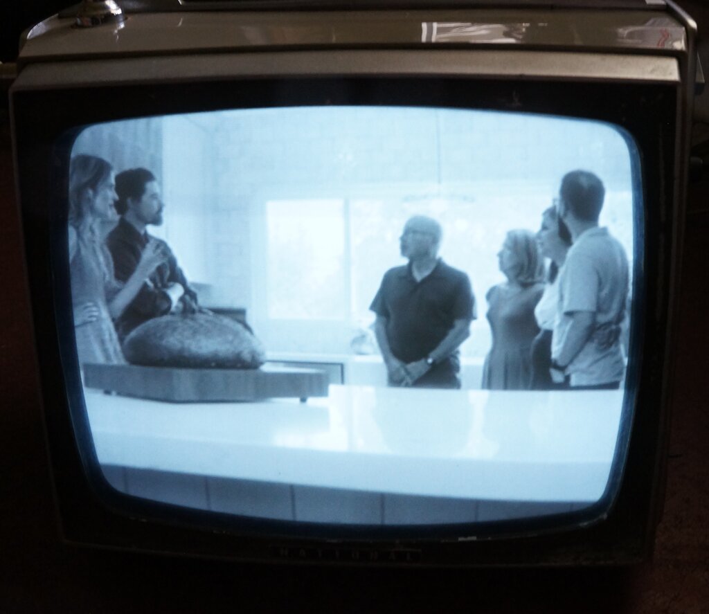
Typical off air picture. Quality is slightly degraded by the camera
and the plastic safety glass.
At last the set was working really well,
but the question has to be asked - how long had the set been operating
with these faults for without anyone being able to fix them?
Curiosity got the better of me, and I
wanted to find out what channels the set could receive. The M69 video modulators
I use cover all the European, U.S., and Australian channels. I was quite
surprised that it received all the Australian VHF channels.
One can only assume the tuner had been
especially made for this set as sold in Australia, and was not as is often
the case, just a European type which won't work in rural areas using channels
3,4,5, and 5A.
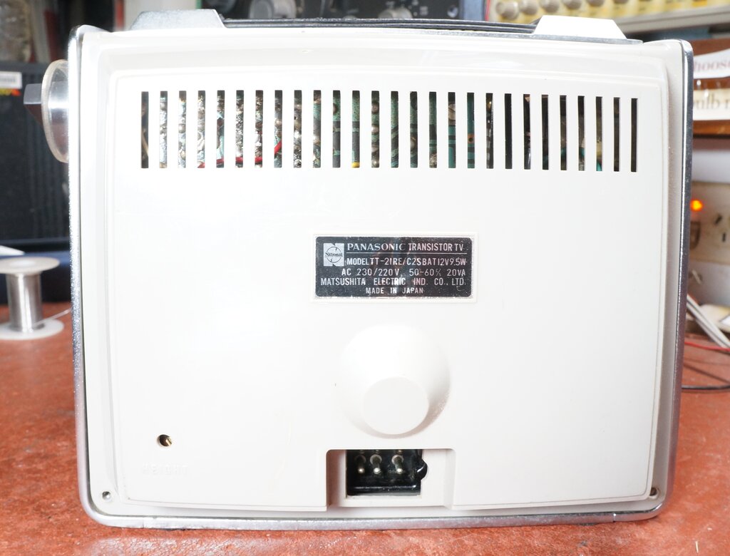
For the sake of completeness, here is the not very exciting back.
Note the 6 pin power socket.