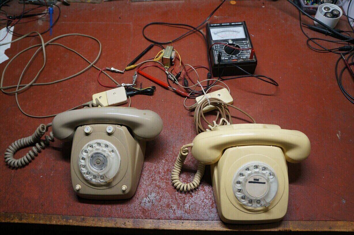
Test set up for the ETI-291 intercom.
Test set up for the ETI-291 intercom.
With the prevalence of dial telephones
now left over because: 1) mobile phones have virtually ended land lines,
and, 2) many commercial services require tone dialling, the question
arises, what can you now do with them?
They can in fact still be used as a landline
phone on the internet via a VOIP service. In Australia, that means using
the NBN. The NBN modem has a telephone connection which is activated if
you have a home phone plan. Since tone dialling is required with most modems
(and to make the phone practical to use), a Dialgizmo is required to convert
the dial pulses to tones.
Home Telephone Exchange.
If you don't wish to use them as a land
line to the outside world, it's possible to set up a domestic exchange
which allows nine phones to call each other.
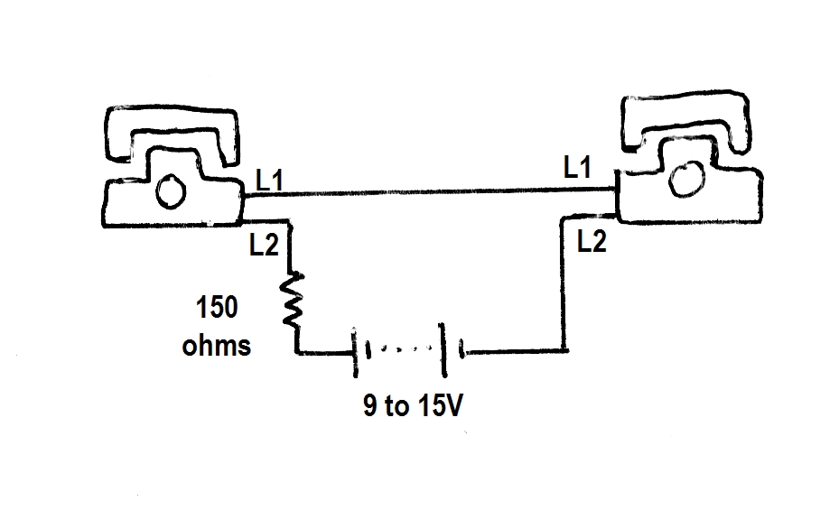
Simple series connection operates the speech circuit, but does not
provide for signalling.
L1 and L2 are the two line connection designations to each phone. Sometimes they are designated as A and B, or L+ and L-.
The method of connection is quite different
to that used with a conventional exchange, but need not concern us here.
When both phones are off hook, about 25mA flows through each phone. The
speech circuitry operates normally, and a conversation can take place between
the two. The limitation is that no signalling is possible between the phones.
The 150 ohm resistor is for current limiting. If, for some reason, the
dials of both phones should be operated at the same time, the power supply
would be short circuited. There is the possibility of damaging the phones.
However, in practice it's unlikely to
happen, since operating the dials does not achieve anything with this circuit.
If one is prepared to risk it, the circuit can be further simplified by
removing the 150 ohm resistor. In this instance, the supply voltage should
be 6 to 9V.
Dry cell batteries are ideal for the circuit,
since they provide hum free operation, and will last their shelf life because
of the low current drain. (Best not to use alkaline cells for the long
term, because they're likely to leak - use carbon zinc or lithium instead).
Plugpack eliminators can also be used, provided the output is well filtered.
Both automatic or central battery telephones can be used with this circuit. As it lacks signalling facilities, it has no practical application beyond proving the concept, or providing amusement.
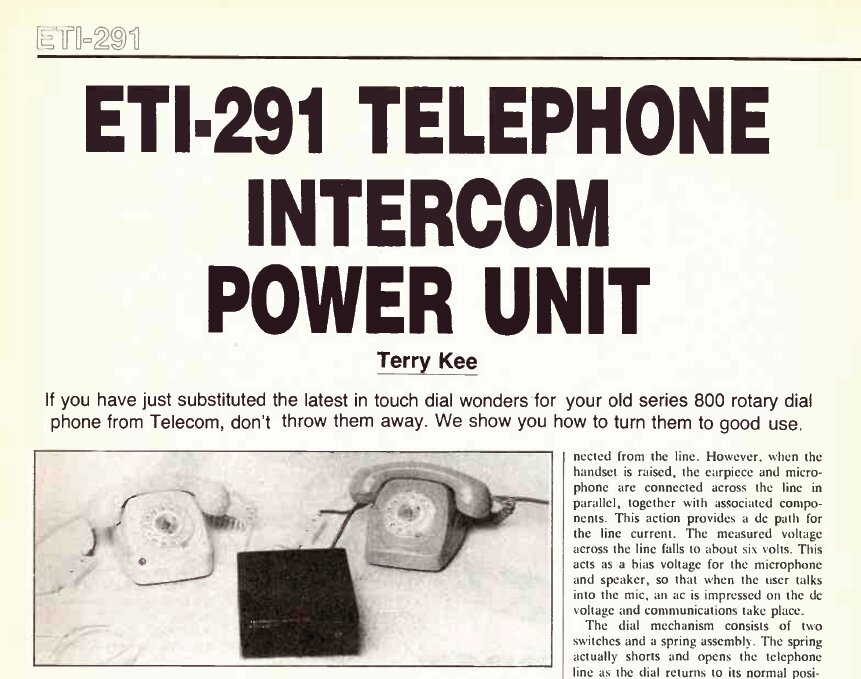
Improved Two Telephone Intercom.
In February 1988, ETI described a simple
two telephone intercom.
Speech Circuit.
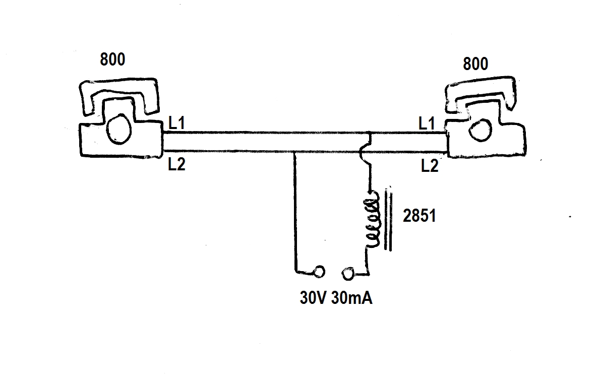
The two telephones are simply connected
in parallel together. They are then connected to a 30V DC power supply
through an audio choke. The choke provides three functions: 1) its DC resistance
limits the current to each phone, 2) the inductance isolates the speech
signal from the power supply, and 3) the back EMF generated by the inductance
during dialling increases the 'ring' voltage to about 45V. The choke used
here is the 240V winding of a 2851 power transformer.
If one phone is taken off hook, about 30mA of current will flow through the choke and the phone. AC voltage corresponding to speech will be present across the choke, and the line to the other phone. Now, if the second phone is taken off hook, its speech circuit is connected directly to that of the first phone. Speech from the first phone will thus be heard in its receiver. The DC supply current will also be divided between the two phones.
A limitation of this arrangement is that one phone might 'hog' most of the DC current, leaving not enough for the other. Lack of current results in poor transmission. In a 'proper' design, each phone would have its own choke, and the speech circuits would be coupled via a capacitor. This way each phone gets its optimum current without upsetting that of the other. Therefore, the phones used with this circuit should be of the same type.
Ringing Circuit.
Some of you may remember back to the days
when the 300/400/800 series phones were to be seen in every house, and
occasionally you may have heard bell tinkling coming from another phone
when someone was dialling out. More than likely, the 'extra' phone had
not been legally installed by the PMG/Telecom. Because, if it had, you
wouldn't have heard the tinkling. The reason being, most 'illegal' installations
were not done correctly. The extra phone was simply paralleled across the
line. As far as the dialling and speech circuits were concerned, everything
worked normally. However, the problem was that with this 'two wire'
connection, the line being shorted and opened on each dial pulse would
cause the bell capacitor in the other phone to charge and discharge. Since
the charging current flows through the bell, the bell responds by tinkling.
The correct way to have done the installation is with a 'three wire' connection,
where the bell circuitry is isolated from the speech/dialling circuit.
More details on this is covered here.
The point here, is this 'incorrect' connection is deliberately used in the ETI-291 for the purpose of bell ringing.
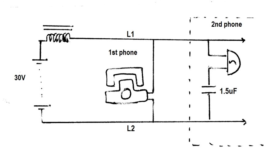
Basic bell ringing circuit.
Looking at the above diagram, we can see the 1.5uF bell capacitor in the second phone is charged to 30V via the current flow through the audio choke, and the coil of the bell. When the dial of the first phone is taken around to the finger stop, there is a short circuit between L1 and L2. The fully charged capacitor is therefore connected directly across the bell, causing it to strike the gongs. When the dial is let go, the connection between L1 and L2 is now open circuit for a brief moment. The 30V supply now charges up the 1.5uF again. Since the charging current flows through the bell, it strikes the gongs, yet again. As the dial continues to rotate back to its resting position, it briefly short circuits and opens the line again. This opening and short circuiting of the line occurs as many times as the digit dialled.
The ETI Design.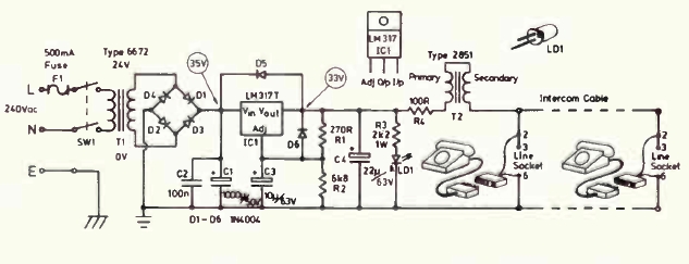
Circuit of the ETI-291.
It could be argued the design of the power
supply was overkill. Firstly, the 6672 mains transformer was vastly bigger
and more expensive than needed, seeing that only about 30mA is required
- or 50mA if you include the power LED. The 6672 is rated at 1A.
The supply did not need the complexity
of the regulator, although it is true that it guarantees a hum free speech
circuit. Incidentally, there isn't much headroom for the regulator as shown,
but to increase the voltage at the input would risk exceeding the ratings.
What could have been done was to use the
30V tapping on the transformer, to provide 42V DC, and filter it with a
simple RC circuit - taking advantage of the higher voltage available.
The choke was actually a 2851 power transformer.
For those outside Australia/NZ, the 2851 is a very common 240V to 12.6V
CT 150mA transformer. It has been a standard, particularly for magazine
projects, since the late 1960's. As can be seen, the primary is connected
in series with the secondary to obtain more inductance. Obviously, the
windings must be phased correctly. It is hardly worth the effort to use
the secondary this way, since it has only 1/20th the number of turns as
the primary. This was confirmed in practice. Inductance of the tested transformer
was 8H.
R4 is a 100 ohm resistor in series with
the 'choke'. Its inclusion is pointless, since the 2851 primary already
has 930 ohms of DC resistance (on the measured example). Nevertheless,
there's no harm in leaving it in if one feels obliged to.
It would be practical to operate the circuit from four series connected 9V batteries (without the LED), and save a lot of construction work. But, as the intention was to simply place the unit out of sight without ever having to look at or maintain it, mains operation is probably the better choice. No doubt, a commercially made 30 to 35V supply could be used instead to reduce the amount of work building the unit. A higher voltage supply would be quite in order, with some improvement to the ringing. Up to 50V is acceptable, but the choke resistance must be high enough to limit the line current to around 30-40mA. If not, extra resistance (R4) needs to be included.
Performance.
How good is it? It certainly works, and
quite well at that, provided certain things are taken into consideration.
The important part here is the ringing operation. As can be seen, it was
intended that 800 series telephones were to be used. This is wise advice,
because it was found that other types were not entirely reliable.
A series 400 phone was tried as one of
the phones, and did work quite well, both on receiving and making a call.
Another 400 was tried, but with unsatisfactory results. However, its dial
was obviously in need of repair. Even so, its bell was not as responsive
as the first 400 tested. Quite possibly, the bell could be adjusted to
improve this. A series 300 phone was not usable at all, but again was in
questionable condition. An Ericofon was also tested, but was unable
to make the 800 ring. Presumably, there was some difference with a damping
circuit associated with its dial, which reduced the rise time of the dialling
pulses.
The Ericofon buzzer did respond to dialling
pulses from the 800, but in typical fashion, would not be heard except
in a quiet room.
Electronic phones were not tested, for
the simple fact these are naturally unresponsive to dialling pulses, since
they are designed for 'two wire' operation. Similarly, it should be obvious
that fax machines, answering machines, or other telephone accessories will
not work. Telephones intended for the U.S. market, or other countries with
two wire working systems will probably not work.
If you have a couple of series 800 phones
looking for a use, the design is ideal for the job.
Connections.
For the series 800 telephone, the connections
are as follows: L1 (L+) is the white wire connected to pin 2 of the plug.
For the bell to ring, pin 2 should also be connected to the red wire at
pin 3. Normally, there is a strap in the socket between pin 2 and 3 for
this purpose. L2 (L-) is the blue wire connected to pin 6 of the plug.
The black wire (if fitted), connected to pin 5 is not used. Some phones
might also have a green and orange wire, which are also not used. Note
that if the telephones used have come from a parallel (three wire) installation,
various jumpers inside the phones will have to be rearranged, to bring
the phone back to single connection operation.