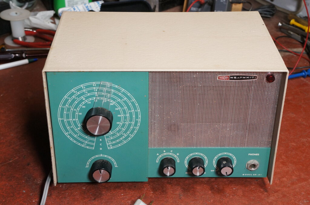
Heathkit GR-81 after restoring knob and dial pointer.

Heathkit GR-81 after restoring knob and dial pointer.
The Heathkit GR-81 is a three valve regenerative receiver kit, covering 150 kHz to 18 MHz in four bands. It was intended as a low cost entry into the world of short wave listening, and was sold from 1962 until 1971. The set uses a 12AT7 as a regenerative grid leak detector, and first audio. Audio output is a 50C5, and the rectifier is a 35W4. Despite the latter two valve types, the set is transformer isolated, as per Heathkit's policy. The mains supply is rated at 105-125V, 30W, 50/60 cycles. Some Heathkit models did have a transformer with two primary windings, which could be connected in series for the 220-240V export market, but unfortunately the GR-81 is not among these. It's a simple matter to use an external transformer, however.

From the March 1962 catalog.
This set kindly came to me from Lance Neame
(ZL3LAD), who I've mentioned in these pages before. Being a valve regenerative
set, I was of course interested to see how it was constructed, and to evaluate
its performance. I've worked with regenerative receivers for just over
40 years now, so I'm familiar with what the performance should
be like. It is always interesting to compare sets, because there can be
considerable variation in performance. Some sets are so badly designed
that the user is scarred for life, and refuses to touch a regenerative
receiver again, while others are a joy to use, and can approach superhet
performance.
Whilst the GR-81 was on its way from NZ
to Australia, I took some time to learn about the set, locating the manual,
and learning of others' opinions of it.
First Impressions.
It was in very good condition cosmetically,
but three obvious things needed dealing with. The dial pointer was missing,
one of the other knobs was missing its aluminium insert, and one of the
feet was broken. I powered it up as is, and was rather surprised to find
the MW broadcast band was received rather poorly. The 5 kW commercial stations,
about 60 km distant, were audible in a quiet room with the volume full
on, but that was all. The 50 kW ABC stations, slightly closer, were a lot
better, but the performance as a whole was vastly inferior to, say, the
Radio TV & Hobbies "Three Band Two", or "Tiny
Tim II". Some airport beacons could be heard on the low frequency band,
but nothing on SW. It is true that less is heard on the SW bands during
daylight, but there should have been something.
Clearly, it was not as it should be, but
before getting ahead of myself, something had to be done about the dial,
because it was completely impractical to tune the set without it.
The whole thing is very well made, being
entirely of steel construction, and of attractive design. Sometimes Heathkit
kits were available already made up, but I can't tell with this receiver.
If it was a kit, the constructor did an excellent job with it.
Dial Pointer.
Sets with dials of this type often have
a vernier arrangement, where the knob drives the variable condenser through
a reduction drive; typically of about 3:1. The pointer is attached to the
variable condenser. I assumed I'd need to make a new pointer to attach
to the variable condenser, but when I took the knob off, it was clearly
otherwise. The GR-81 uses the simpler method, whereby the pointer is attached
directly to the knob, and rotates with it. However, there is some reduction
after the knob, of almost 2:1. This is evident by the dial scale being
slightly over 300 degrees, rather than the usual 180 degrees, when the
tuning condenser is directly driven. To compensate for the low ratio of
reduction, a fine tuning control is provided.
Why the pointer was missing is unknown;
I know nothing of the set's history. According to the manual, it clips
into the rear of the knob inside the skirt. The knob would have had to
have been removed for it to go missing. Anyway, mysteries aside, what to
do about it?
The pointer is usually clear plastic or
celluloid. Looking through suitable pieces of plastic, I decided on a piece
of perspex from a parts drawer divider. I've used this material for dials
before.
Scaling from photos on the internet of
intact GR-81's, I worked out a suitable set of dimensions, and cut the
plastic suitably. To get the line up the middle, I simply used a scriber
to scratch that in, and then filled it with a white wax pencil.
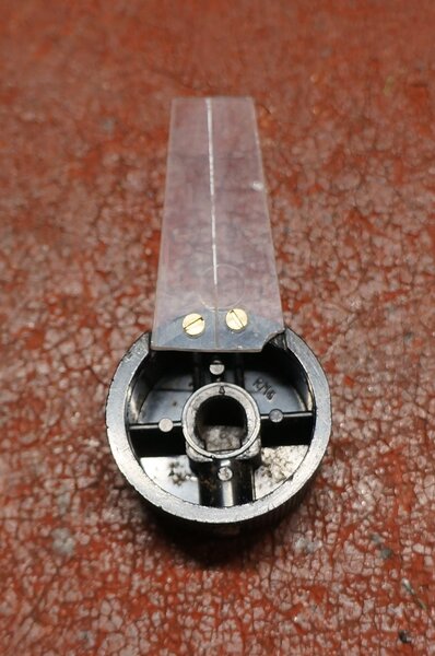
New pointer attached to knob. Ignore the chipped off piece - it's
not visible.
How to attach the pointer required a bit
of thought, since I couldn't reproduce the original clip in moulding. The
end result was the simplest. The knob skirt was actually thick enough to
take some 10 BA screws, so I simply drilled and tapped for those.
Since the tuning shaft is so short, the
knob can't be very much off the front panel, or the grub screw will have
nothing to engage against. Therefore, the knob skirt was filed so that
the pointer was flush with the edge. The 10 BA screws were countersunk
as well.
Once assembled and installed, it looked
just as good as the real thing, and the receiver could now be properly
tuned.
Knob Insert.
One of the control knobs was missing its
aluminium insert. While not essential, it looked out of place, and I thought
I should be able to make one. I used a Whitney punch to create the aluminium
disc. The slot was cut with a flat file, and the rounded section at the
end was made with a jeweller's file. Being slightly oversize, I then filed
the edge of the disc until it was a press fit into the knob. Once installed,
it was hard to tell which knob it was.
The broken foot was repaired with polystyrene cement. No electrical restoration was required, since the one and only paper capacitor (C8) is in a non critical location, as far as any leakage is concerned. All the carbon resistors measured slightly high, but not enough to warrant replacement in this kind of circuit.
Frequency Ranges:
Two aerial terminals are provided, designated
"Long Antenna" and "Short Antenna". The long antenna terminal connects
to the required coil via one pole of the four position rotary switch. Interestingly,
for Band B (MW broadcast band), there is a .001uF condenser in series
with the aerial connection. My guess is this is to compensate for very
long aerials, where there can be an absorption effect. When this happens,
the aerial resonates with the coil around a certain frequency, and regeneration
is difficult. By inserting a suitable capacitor, the resonant frequency
is shifted out of the band, removing the 'suck out' effect.
The short antenna terminal connects the
aerial straight to the tuned circuit secondary via a 12pF condenser. This
provides a much tighter coupling than the separate primary winding. Its
disadvantage is that the aerial loading affects the tuned circuit, and
in simple sets like this the dial calibrations shift slightly, because
of the added capacitance from the aerial.
The intention is to use the "long antenna"
for long wire aerials of significant length. In this regard, Heathkit mention
50 to 1000 feet (15 - 300 m). Less than 50 feet (15 m) is considered a
"short" antenna. Heathkit suggest that bands A and B are
used with a "long antenna" connected to that terminal. Bands C and
D
should be used with a "short antenna" and connection.
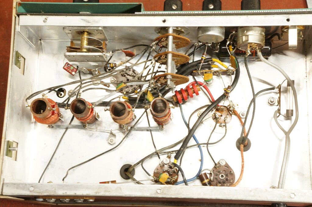
Tuning coils and rotary switch are visible here.
Detector.
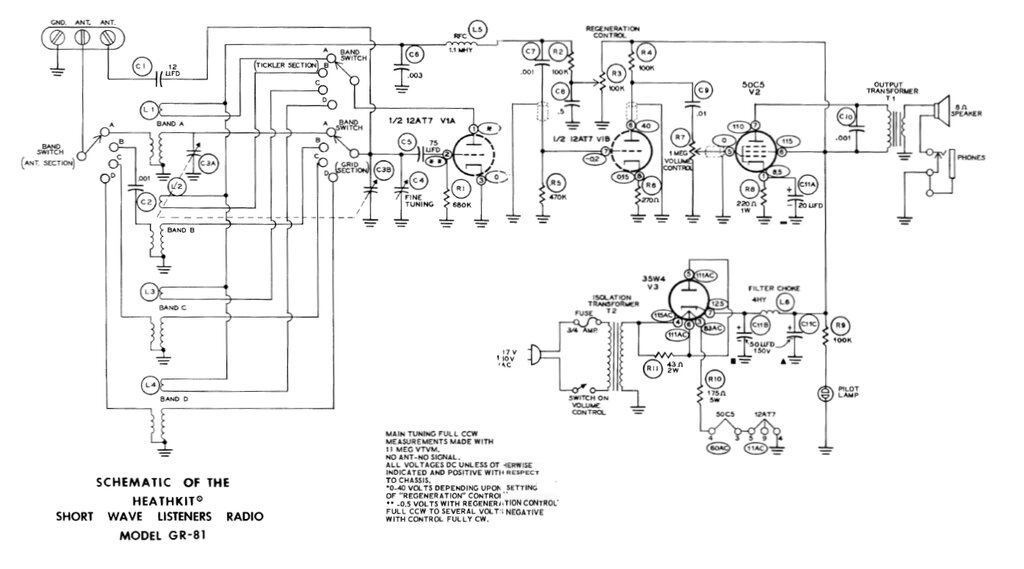
One triode of the 12AT7 functions as a
conventional grid leak detector. The grid components being the 75pF capacitor
and 680k resistor are probably selected more for the SW bands. For MW and
LW, these components would be typically doubled.
Grid leak detectors work on the principle
that a diode is formed between the grid and cathode, so that rectification
of the RF signal takes place. Since the valve is a triode (or pentode),
when the signal is extracted from the plate, the detected signal is amplified
by the audio gain of the valve.
Additional gain comes from regeneration,
which is really just positive feedback. By introducing a controlled amount
of positive feedback, a small signal coming into the detector will be amplified,
and when fed back into the input will be stronger again. The process is
repeated again and again, resulting in a very high gain. However, if the
process is allowed to continue ad infinitum, the gain will become so high
that the detector will then oscillate, making reception of AM (or FM)
signals impossible. The idea therefore, is to keep the amount of feedback
to just below the oscillating condition.
Positive feedback is obtained with the third winding, in the 12AT7 plate circuit. As well as detected audio, the plate circuit also has an amplified amount of RF present, and it is this which is fed back into the coil. The feedback coil is phased with respect to the grid coil so that feedback is positive and not negative. Numerous methods exist of controlling the feedback, and the one used here is to vary the plate voltage of the detector by means of the 100k pot (R3). This gives very smooth control with no backlash. Another popular method is to include a variable condenser in series with the feedback winding; the reactance of which adjusts the amount of RF current flowing through the winding. It usually suffers terrible backlash, and the varying of capacitance has some effect on the main tuned circuit. I do not recommend this method.
Note that regenerative detectors are used in an oscillating condition to demodulate CW or SSB signals. In this regard, the detector is also functioning as a BFO to recreate the carrier frequency,
The detector plate load is 100k (R2) and it is here the detected audio is made available. Any RF is bypassed by the .003uF (C6) and further filtered by the 1.1mH choke (L5). From here, the audio passes to the second 12AT7 triode for further amplification. The .001uF coupling condenser (C7) is rather low, and would tend to attenuate the bass response. I would assume this was done to reduce the effects of power supply hum.
Audio Stages.
The second 12AT7 operates as a normal
voltage amplifier. The cathode resistor is not bypassed, possibly for stability
reasons, but in reality the amount of signal lost here would be insignificant,
comparing the ratio of the 270 ohm cathode resistor to the 100k plate resistor.
A bypass capacitor would achieve very little.
From the 12AT7 plate, the signal proceeds to the volume control, and thence the grid of the output valve which is a 50C5. This operates under conventional conditions. With the preceding plate load being 100k, the volume control could have been of a lot lower resistance than the chosen 1M. This would have the advantage of reducing grid emission from the 50C5; something which could be possible because of its high heater power (7.5W). As it is, a lot of the time because of the low gain, the receiver is operated with the volume control close to full on (i.e. with the full 1M resistance). Volume control values as low as 100k would be suitable.
One strange aspect of design is the headphone socket. It's wired so the speaker is in series with it. When the phones are not plugged in, the socket contacts are shorted, completing the speaker circuit to earth, and it works normally. When phones are plugged in, they are in series with the speaker. With low impedance phones (e.g. 16 to 32 ohms), a substantial amount of the audio will still be heard from the speaker. However, during the 1960's most headphones were high impedance (e.g. 1000 ohms), and this will reduce the effect, but not eliminate it altogether. In other words, the design does not allow for completely private listening. Why Heathkit chose this method is a curious thing, but they do imply the use of an extension speaker along with the receiver's speaker at the same time.
Regarding the speaker mounting, it is not flush against the front panel. There is a slight air gap which reduces the baffling (and low frequency response). This comes about because of the mounting screws themselves having to be flush with the front panel, in order to accommodate the speaker grille. A gasket could have been fitted between the speaker and panel to eliminate the air gap. I have not tested how important this actually is.
Power Supply.
The set is fed from a 1:1 isolating transformer,
but otherwise follows the usual series heater type power supply. The heaters
are in series, which add up to 97.6V. A 175 ohm dropping resistor takes
up 26.3V, to allow for a total voltage of 124V.
The 35W4 half wave rectifier provides
the 115V B+ via a choke capacitor filter. Usually, resistor filtering is
used with these cost cutting designs, so it is interesting to see Heathkit
have used a choke. Mains hum is certainly minimal.
Normally, the 35W4 is used in conjunction
with a 6.3V 150mA dial lamp connected across part of its heater (pins 4
and 6). Since this set does not use such a lamp, a 43R resistor takes its
place. The 35W4 can also be used without the dial lamp tapping, but a resistor
is still required to limit the peak plate current. Some info on the use
of the 35W4 is here.
On the subject of dial lamps, it is a peculiar feature of this set that
a neon lamp is used, which takes its supply from the B+. The result is
confusion when the set is first switched on, because there is no light
until the valves have warmed up. It's also a possible safety hazard for
someone unfamiliar with the set working on it, thinking it's not powered
up when it actually is. Why wasn't the neon lamp powered from the AC?
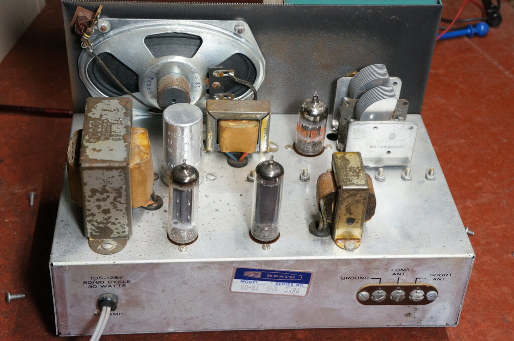
Rear view of the GR-81.
It appears the lack of sensitivity with the "long antenna" connection is because the spacing between the primary and secondary windings is greater than it should be. At a glance it looks to be about 8mm, whereas coils which I've used with good results have had about 3mm spacing.
There's not much on SW worth listening
to these days. In this part of the world, the 6-18 MHz band is mostly occupied
by Chinese broadcasters. I did however discover an interesting Australian
station playing music on 4970 kHz. I can't find much about this station
except it's at Wee Waa, which is 515 km to the north of my location. It
has a minimal web site here https://radio567.com.au/
Anyway, that was a nice surprise, especially
as some of what is played is my kind of music.
Aside from 4970 kHz, nothing was audible on SW during the day. Even then, 4970 kHz only comes in from the late afternoon.
At night time, the SW bands come alive, and even with the "long antenna" connection, plenty is receivable; albeit mostly Chinese. I was able to receive some SSB in the 3.5 MHz amateur band.
My summary of the aerial connections is this: Unless you have a super long aerial, or are in a strong signal area (i.e. within about 10 km of MW stations), use the "short antenna" connection, even though you're using what would be considered a "long antenna". In my area, I cannot see any use for the "long antenna" connection at all with my 40 m aerial.
I attempted to perform sensitivity tests, but found this very difficult, possibly because of the matching between the signal generator and the receiver. In some instances, the detector would not oscillate. Subjective results were a variation of 300uV to 2.3mV over the complete tuning range. This was via the "short antenna" terminal, and with 3V p-p of detected audio at the volume control input. Figures like that don't imply a huge amount of sensitivity, so this receiver relies more on the aerial than anything else.
An interesting quirk which is mentioned
in the manual, is that super-regeneration can take place beyond 10 MHz.
This did bring up the sensitivity to about 14uV. How well it goes into
super-regeneration is very dependent on aerial loading. Quench frequency
was around 32 kHz.
There is no quench filtering however,
but the audio stages functioned well enough. As expected, the tuning broadens
once the detector goes into super-regeneration.
Dial Calibration.
Tests were made using both aerial connections
to ascertain the accuracy of the dial calibrations.
| Sig. Gen. | Band | Dial (Long Ant.) | Dial (Short Ant.) |
| 150 | A | 152 | 155 |
| 240 | A | 245 | 250 |
| 500 | A | 515 | 590 |
| 600 | B | 595 | 605 |
| 900 | B | 890 | 910 |
| 1600 | B | 1600 | S.G. 1540, dial 1700 * |
| 1700 | C | 1700 | 1720 |
| 3.0 MHz | C | 3.0 | 3.1 |
| 5.0 MHz | C | 4.95 | 5.45 |
| 5.5 MHz | D | 5.48 | 5.55 |
| 9.0 MHz | D | 8.9 | 9.2 |
| 17.0 MHz | D | 16.2 | S.G. 16.2, dial 18 * |
*Dial did not have enough range for the received frequency (S.G. = signal generator).
One of the limitations of the GR-81 is
that the coils are not adjustable. Consequently, the dial calibrations
are only a guide. The coils could have been fitted with adjustable ferrite
or iron dust cores, and trimmer capacitors. This would have allowed the
dial calibrations to be more accurate, on the "long antenna" connection
at least. Possibly, the assumption was that constructors of a set like
this would not have facilities for alignment, and that adjustable coils
in the hands of the inexperienced could thus lead to an even greater discrepancy
when randomly adjusted. Outside of the MW band, the signals are too sporadic
and of unknown frequency to perform off air alignment with.
There is also the effect of 12pF added
to the tuning circuit when the "short antenna" is used. This is clearly
evident in the above table. The only way to ensure accurate dial calibration,
regardless of aerial type would be to include an RF amplifier stage - but
that's getting beyond the aim of this set.
MLA 30+ Loop Aerial.
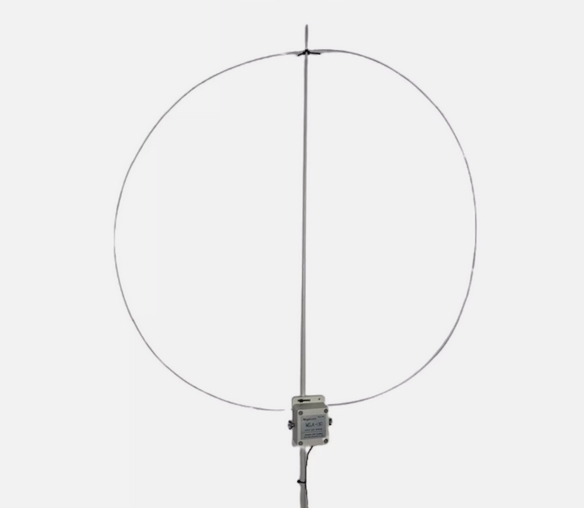
The MLA 30+ works well with the GR-81.
Since it was conveniently to hand, I tried
a MLA 30+ active loop aerial. This aerial runs off 5V via a USB connection,
and contains a high frequency op-amp of the 733 type which is located in
the aerial connection box. There's also an adjustable gain control in the
same box.
Connection is best with the "short antenna"
terminal.
Results with the GR-81 were very good,
both on MW and SW. The aerial is very directional, which can be put to
good use for interference reduction. If you're thinking of getting a GR-81,
and don't have room for a long wire aerial, the MLA 30+ is a good alternative.
In fact, it's worth getting one anyway, even if you do have a long wire
aerial! They're all over eBay, so one can shop around for the best price.
Summary.
If the limitations are taken into account,
it's a nice little set that does its intended job. It must have a good
aerial - the performance is entirely dependent on it. The dial calibrations
are only a guide - do not expect complete accuracy. The audio is not hi-fi,
with a lacking of bass response, but it is clear. The best performance
is the MW band, and in these days of decreased SW broadcasting, this is
where it's most likely to be used anyway.
