
Completed receiver built in diecast box.

Completed receiver built in diecast box.
This project was described in the March 1979 issue of "Electronics Australia". It is one of those projects that had been on my 'to do' list for many years. I'm not really sure why I took so long to get around to it, since I would have been aware of it back in 1987, when I first started building VHF receivers. For those outside of Australia and New Zealand, "EA" as it was known, was the leading Electronics magazine for many years, and was responsible for a very large kit industry among the various electronics parts retailers.
The design we're looking at here is a three transistor regenerative receiver for VHF. It is based on a design originally described in the English magazine, "Radio and Electronics Constructor", for May 1978. This in turn, was based on a previous design in the same magazine, presented in January 1974.
Regenerative and Super-Regenerative
Receivers.
The two types of receiver, regenerative
and super-regenerative, while schematically very similar, are completely
different in their operation. Regenerative receivers work by means of a
controlled amount of positive feedback. An RF amplifier (which may be part
of the detector) has a portion of its output fed back into the input, phased
so the feedback is positive. Any signal coming in is amplified, so that
the signal at the output of the RF amplifier is now greater. If a portion
of this is fed back into the input of the amplifier, the input now sees
an effectively stronger version of the same signal. The process repeats,
and the signal at the output of the amplifier becomes larger and larger
until the amplifier starts oscillating.
The signal is of no use now, but if the
amount of feedback is controlled so that it remains just below the oscillation
point, the output of the RF amplifier provides a much stronger signal than
it would without any feedback.
The RF amplifier output is fed into an
AM detector in the usual way. In most regenerative circuits, the RF amplifier
and detector are part of the same stage. Generally, the RF amplifier is
biassed to class B so it conducts more on one half of the cycle, and thus
detects AM, or in the case of most valve designs, the diode formed by the
grid to cathode circuit provides detection.
Super-regenerative receivers also have an RF amplifier with positive feedback. In this case, the amplifier is adjusted so it always oscillates at the receiving frequency. However, the oscillation is interrupted at a much lower frequency by a quench oscillator (25kHz is typical). If a signal is fed into the oscillator during the period where it is switched off ("quenched"), it will trigger it, causing it to start oscillating slightly earlier on. Thus, the period of oscillation is lengthened before it is switched off again by the quench circuit. Detection is achieved by sampling the average oscillator supply current. The longer it oscillates, the more current it draws over a given period of time. The stronger the signal, the earlier the oscillator is triggered, and the weaker the signal, the later it is triggered. Hence, AM detection occurs, since the carrier varies in strength at the modulating frequency.
Super-regenerative receivers have a greater sensitivity than the ordinary regenerative type. However, there is an optimum ratio between the RF and quench frequencies, and below about 20MHz, the optimum quench frequency becomes audible. For this reason, optimum performance cannot be obtained in the MW broadcast band, for example. Another characteristic of the super-regenerative receiver is its wide bandwidth, which means it has poor selectivity; again not being suitable for the MW band. While unsuitable for closely spaced MW stations, this does become a desirable feature for wideband FM reception in the VHF band. Also, the constantly oscillating detector is a potential source of interference.
With these factors taken into account,
tradition has been to use regenerative receivers up to about 30MHz, and
super-regenerative receivers for higher frequencies.
Both types of receiver demodulate AM signals.
They will also demodulate FM if the response curve is suitably matched
to the deviation. By tuning the receiver to the most linear part of the
slope of the response curve, the FM signal is converted to AM. Slope detection
has been covered in the various super-regenerative receiver articles around
this site.
Regenerative Receivers at VHF.
In England and Australia, super-regenerative
receivers were seldom published as magazine projects, as compared to the
U.S. The fear seemed to be one of interference, and home construction was
discouraged. Somehow, the U.S. seemed to get along with multitudes of super-regenerative
receivers, both commercially made, and also described for home construction.
Over its 62 years of existence, Electronics
Australia only described two general coverage super-regenerative receivers;
both being of the Fremodyne
type. This was tolerated, since interference was confined to the 27MHz
'garbage' band. There were a couple of VHF and UHF receivers presented
in the early days of these bands for amateur use, but the implication was
they were purely experimental, and to be abandoned as soon as superhet
techniques became practical.
From time to time, circuits for simple
TV sound receivers appeared in English magazines, in the early days of
405 line TV, and these were regenerative receivers, operating on the 41.5MHz
London TV sound frequency.
Much later, two solid state regenerative
designs appeared in the 1970's for the FM broadcast band, which will be
described shortly.
There's no reason why the principles of
regeneration cannot be used at VHF, and back in the late 1980's, I did
experiment with an ordinary regenerative grid leak detector using a 6ES8
valve. It worked quite well with certain limits.
Despite EA's insistence that regenerative
receivers were not suited to VHF, it was with some irony that the March
1979 project was presented.
The Radio and Electronics Constructor
Receivers.
Before we get to the EA design, lets look
at it its origins. First, is this design from the January 1974 issue of
Radio and Electronics Constructor:
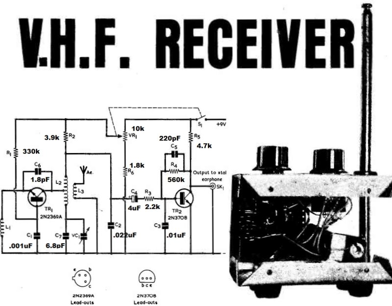
This is a two transistor circuit with TR1
as the regenerative detector, and TR2 as the audio amplifier. TR1 is operated
as a grounded base amplifier, and positive feedback is introduced by C6
between the emitter and collector. This is a very common oscillator configuration
for transistor circuits. Those who have studied solid state super-regenerative
receivers will note the schematic similarity with this circuit. The important
difference is that no proper time constant for self quenched operation
is provided with this circuit.
As can be seen, the receiver is self contained
with a telescopic aerial, and it drives a crystal earphone. Regeneration
is controlled by adjusting the supply voltage to the detector circuit.
The next evolution was in May 1978, with
a FET and two transistor version:

The May 1978 design.
Two changes for the later circuit are the extra audio stage, and that the detector is now a FET instead of a bipolar transistor. The operation is the same, with feedback between the drain and source of the FET. Again, the design included a telescopic aerial, and was intended to drive a crystal earphone.
The EA version was based on the May 1978
Radio and Electronics Constructor design. It was modified to suit local
parts, and to improve the sensitivity.

The most significant change was the use
of a BF115 bipolar transistor instead of the FET, because of its higher
gain. It still operates in grounded base mode, but now requires forward
bias. This comes from the voltage divider consisting of the 22k and 15k
resistors. The base is AC earthed by the .022uF. The previous FET source
load resistor which was 1k is now 10k.
For feedback to occur between collector
and emitter, there has to be a high impedance in the emitter circuit, which
in this case is the 270uH choke. The May 1978 article also has a choke
in this position, but was a home made type using a ferrite core which is
an unknown type here. It was found that a 270uH choke would perform suitably
instead.
Unlike the original English versions,
this wasn't really intended as a portable receiver. It was intended to
operate from a 300 ohm dipole, and as such includes a balun at the input
to the detector.
Another notable change is the stabilised
detector supply, using the 6.8V zener diode. Also, the adjustment of the
regeneration control was spread over a greater degree of rotation by including
the 2.2k and 4.7k resistors either side of it. The pot value was also changed
to 1k.
The audio amplifier is the same, except
for the 100uF coupling capacitor on the output. This is necessary for magnetic
or dynamic headphones.
Back in early 1979 when this project was designed, FM stations were few and far between in Australia. In Sydney, there was only 2ABC (ABC's classical music station), and 2MBS (a public station with a classical music format). It was suggested that the receiver be used also for listening to two way VHF traffic around 76MHz, and with modification of the tuned circuit, to aircraft and the 144MHz amateur band. Within the FM band in some areas were also the TV channels 3,4, and 5, which would be receivable with this receiver as is.
In 2023, things have changed considerably. The FM band is full of stations, TV has been digital only for the last 10 years, and most two way radio is also digital. Aircraft is still using AM.
The EA version had the components assembled
on tagboard, which was mounted on the box lid via standoffs. I contemplated
making a PCB, but for a project of unknown performance, it would be disappointment
to do all that work if turned out to be an inherently poor design.
Tagboard is still available from Jaycar,
and that was my initial preference. The tagboard which EA used was an Australian
made type, which has the tags spaced closer together than the Jaycar type,
and luckily I had some. This meant I could use exactly the same layout
as the EA version.

Parts gathered for construction.
First thing was to mount the dial, since
everything would be placed relative to this. Also, the regeneration pot,
switch, and headphones socket needed to be mounted. A bracket was made
to mount the tuning condenser, and it was secured by the regeneration control
shaft.
With that done, next was to mount the
tagboard. I don't like lots of screws all over the front panel, so made
up a bracket to mount the tagboard using the same screws for the vernier
dial.

Close-up of tuning condenser bracket.
One slight departure from the electrical design I had to make is with the tuning condenser. Note that the moving plates are connected to the detector positive supply. In the EA design, they used insulators to separate the tuning condenser shaft from the front panel. Since that was not practical here, I simply bypassed the supply positive to earth at the tuning condenser mount with a .01uF ceramic capacitor. Electrically, it functions the same, because the detector supply is AC earthed anyway.
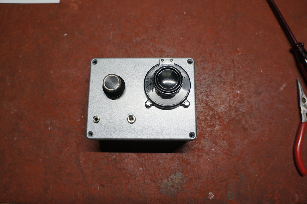
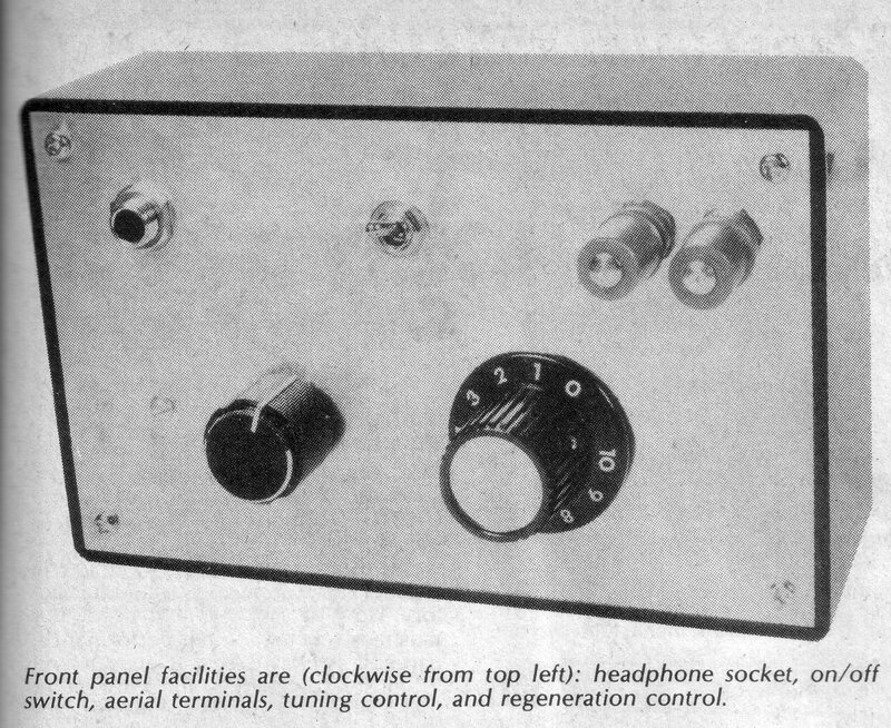
Front panel components mounted.

Tagboard now mounted.
With the front panel complete, next was to wire the tagboard. I used the same layout as EA, except for a couple of minor modifications with the audio amplifier - this being because my tagboard had one less row of tags.
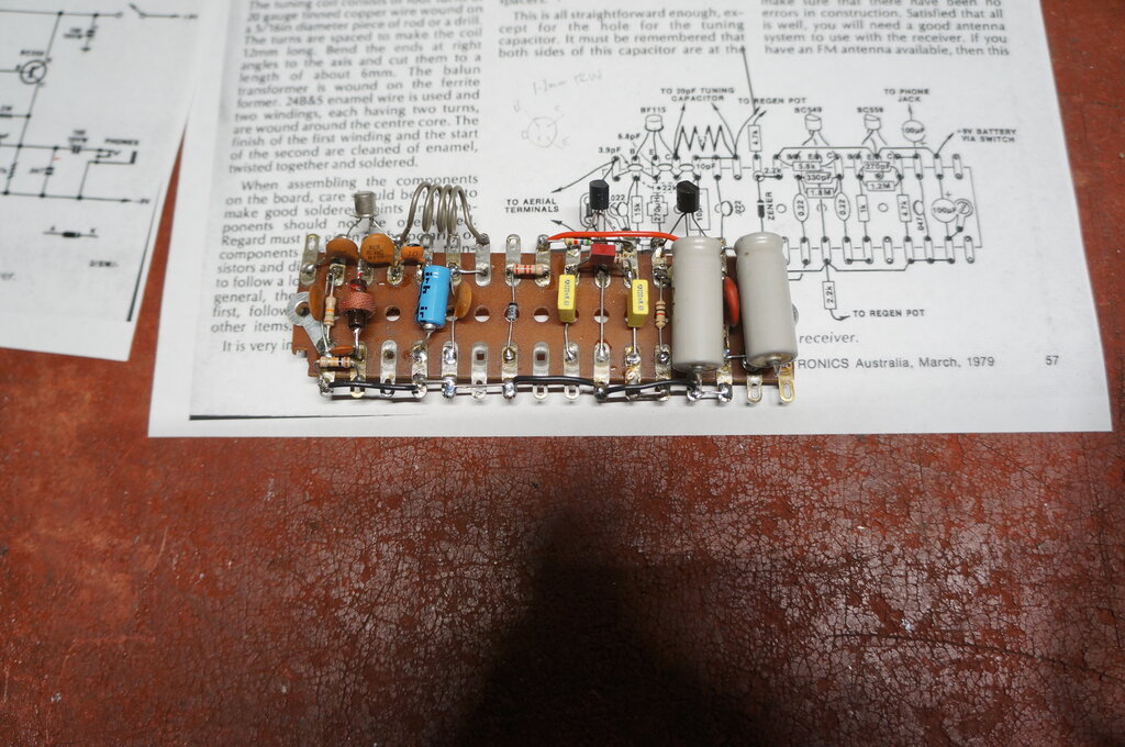
The components were identical, except the
closest choke I had was 220uH instead of 270uH. It was of a type once sold
by Paris Radio, part number VPC220. As far as I could tell from the photo,
EA also used a Paris Radio choke. Incidentally, the VPC prefix comes from
"Video Peaking Choke".
I decided to omit the balun, since the
VHF radio signals are reticulated around the house with coaxial cable,
and it wouldn't be required if I was to use a telescopic aerial.
At this stage, I hadn't given a lot of
thought to the power supply. EA had just used a 9V battery. If the receiver
had poor gain, and would have to always be used with an outdoor aerial,
a DC input socket for a plugpack would be a suitable option. If it turned
out to be OK for portable use, then a battery would be required. As it
turned out, the receiver was certainly usable as a portable, so thoughts
turned to batteries. What would fit, and what would be easy to mount?

Space above regeneration control was used to mount the battery.
Six AAA cells would fit under the tagboard
bracket, so that was an option. I would however have to use lithium cells,
since alkaline cells leak. In the end I just thought it easiest to use
a normal 216 type 9V battery. While the alkaline versions also leak, its
usually a less destructive leakage. And anyway, these batteries are also
available in lithium.
How to mount the battery took a considerable
amount of thought, because the battery can only fit in a certain area,
and then it has to be secured somehow. Again, I didn't want screw heads
protruding, which meant making up another bracket secured by the regeneration
control shaft. This worked out very well. A PCB mount battery holder was
attached to the bracket. Although the bracket is held at only one point,
it cannot rotate because it also bears against the ridge around the box
lid perimeter.
Current consumption is 2.5mA at 9V.
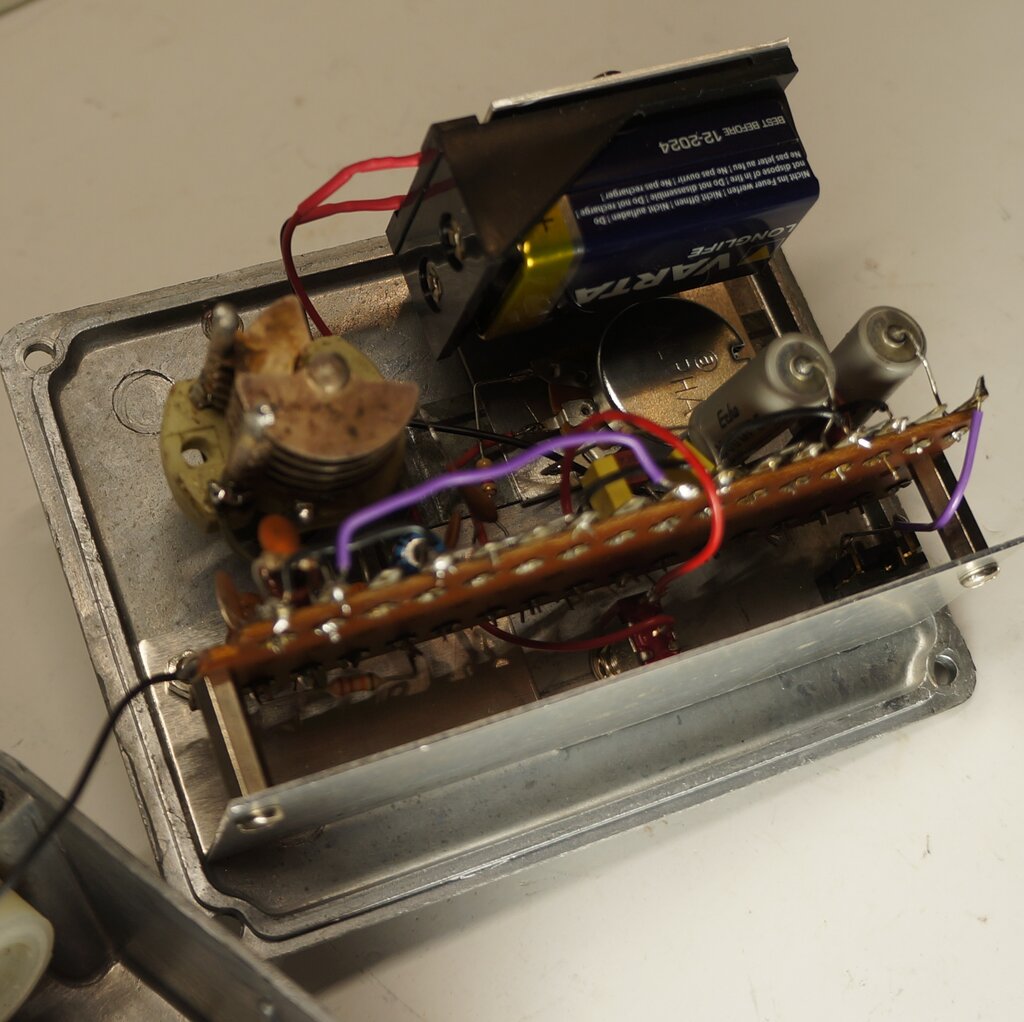
Battery holder mounted.
The final part of construction was the
aerial. Since it had been established, after initial testing, that this
would be a portable receiver, the obvious choice was a telescopic aerial.
These are widely available on eBay, so a suitable type was ordered. Fully
collapsed it had to be shorter than the length of the box. This meant a
compromise with the length fully extended. For the FM band, the ideal length
is 75cm which is a quarter wavelength. The aerial I obtained is only 30cm,
but seems acceptable with the good sensitivity.
How to mount the aerial required some
thought because it has to be insulated from the box. I used piece of nylon
rod with a 6mm hole through the centre. This is a tight push fit for the
aerial base, but it still needed to be secured with a 3mm bolt right through.
Then, a 7mm hole was drilled in the box,
and the nylon mount secured with 2.5mm countersunk screws, tapped into
the nylon.
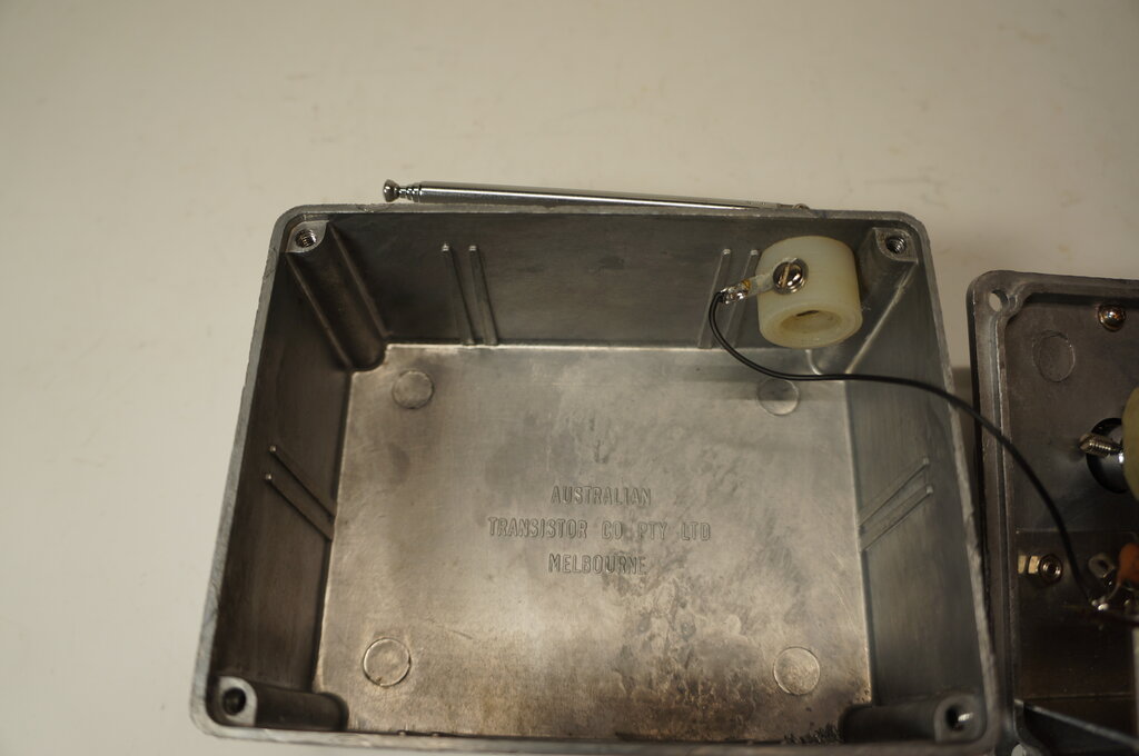
Nylon insulator for aerial.

Receiver with aerial extended.
First power up was with the receiver connected
to my outdoor FM aerial, with its masthead amplifier and six way splitter.
Stations were heard immediately without having to adjust anything. It was
noted that the selectivity was fairly poor, as if the detector was being
overloaded.
The regeneration control was very non
critical. It handles unlike any other regeneration control I have used
previously.
With the typical regeneration control
used in other sets, as the control is adjusted towards oscillation, there
is notable increase in sharpness in tuning, as well as volume, and if taken
too far, the whole thing bursts into oscillation. This is evident by a
strong whistle in the background.
For this set, the sharpening of the tuning
doesn't seem very evident, and when it does start oscillating, it sounds
like a fast ticking sound, reminiscent of a geiger counter. This ticking
sound is due to the time constant of the .01uF and 10k in the BF115 emitter
circuit.
I briefly decreased this time constant,
by changing the .01uF to .001uF to see if it would work as a super-regenerative
detector. It did to a degree, but more optimisation would be required.
There was a bit of a dead spot around
the middle of the band with the regeneration, and rather than experiment
with changing the 4.7k and 2.2k resistors, I just changed the pot to 5k
to give a greater control range. This solved the problem nicely.
With the tuning condenser I used, frequency
coverage is 87 to 110MHz.
Headphones.
Volume through headphones is surprisingly
good, and it was unnecessary to include a transformer. EA's recommendation
was high impedance magnetic phones, or a crystal earphone, but also mentioned
that low impedance phones worked satisfactorily. Obviously, the higher
the impedance, the louder the signal. For the most part, I have been using
some low cost phones once sold by the Warehouse, branded Tech.inc "Verve".
With both channels in parallel, the impedance is 55R. Best phones of all
were the Marley Liberate XL. These are only 55R per channel, presenting
a load of 27.5R, but the sensitivity more than makes up for the lower impedance.
In fact, the two stage amplifier in the receiver works well with these
phones.
Needless to say, with a transformer, performance
is even better. I found best load impedance was around 2k. More on these
headphones can be seen here.
Sensitivity.
This really surprised me. It certainly
was being overloaded by my aerial system, because best results were with
the aerial connection near the tuned circuit, but not actually connected
to the 3.9pF capacitor. In other words, it works best with a very light
coupling.
What I didn't expect was to be able to
tune in all the mainstream stations up and down the coast with no aerial
at all. Distances to here are up to about 130km. The coil has enough pickup
on its own. Of course, once the receiver is inside the box the signal is
severely attenuated, and an aerial outside is needed.
Measured with a R&S SMS signal generator,
it quite easily resolves a 10uV signal, although it is noisy. There is
not the huge difference in sensitivity I thought there would be, between
regenerative and super-regenerative detectors. In view of the good sensitivity,
I felt the shorter telescopic aerial would be satisfactory. Having said
that, any serious reception attempts with low power signals would require
a proper outdoor aerial.
Sound Quality.
While gain increases with the amount of
regeneration, the bandwidth is reduced. This is why best selectivity is
obtained with the regeneration control set to just before oscillation.
This is the ideal reception condition for ordinary AM voice and music reception,
where bandwidth does not need to be more than about 10KHz.
For wideband FM reception, the bandwidth
needs to be about 200kHz. The astute will realise by now, that with a VHF
regenerative receiver, the point at where sensitivity is greatest means
the bandwidth will be insufficient for proper demodulation of wideband
FM.
And so is the case with this receiver.
Least distortion occurs with strong stations, since the regeneration can
be backed off, enabling a wider bandwidth.
The weaker the station, the more distortion
there is, since the regeneration has to be advanced further to hear it.
With careful tuning adjustment, and using
the minimum amount of regeneration, it sounds quite good on some stations.
It tunes like any other slope detecting FM receiver, in that the signal
is received either side of the carrier.
Note that since this is a regenerative
receiver, there is no hissing noise, as with a super-regenerative receiver
on a weak signal. Overall though, a super-regenerative receiver is less
distorted with its wider bandwidth, on both strong and weak signals.
In Summary.
It was an interesting project, and it
answered the question I've always wondered of how good its performance
was. While the sensitivity is quite good, the problem is that to actually
use it at the most sensitive point, means listening to distorted sound.
A regenerative receiver for wideband FM
really finds its place only for strong signals. In this instance, it has
the advantage of no intermodulation distortion, or beating with the stereo
pilot tone, as can be problematic with super-regenerative designs. It is
also much quieter than a super-regenerative receiver.
The regeneration control is a minor irritation
because it goes into oscillation abruptly. In fact, if the control is set
close to oscillation, it may actually go into oscillation on modulation
peaks. Also, moving the set, or the headphone lead (acting as a counterpoise
earth), can also make it go into oscillation as the signal strength varies.
However, this is not important with strong stations, since the control
is not set near oscillation.
