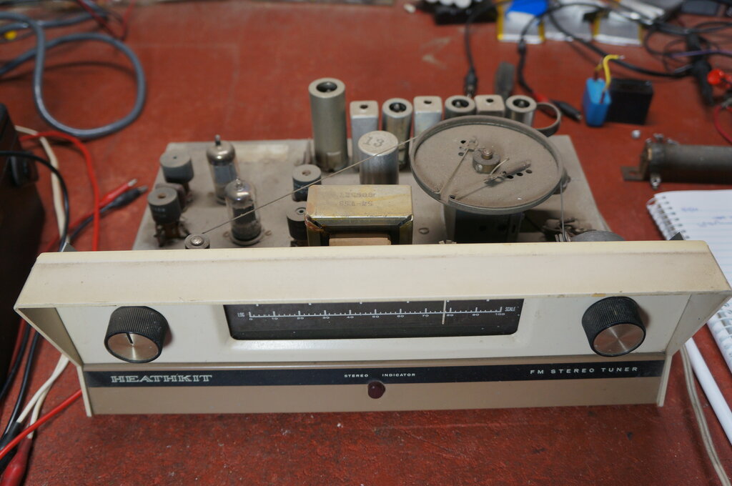
This tuner was selected for testing since it has a transformer power supply.
The best and safest way to operate 120V appliances on 240V is with a stepdown transformer. This should be double wound to provide isolation. The use of a cheaper auto-transformer does not provide isolation. The problem here is that the output can be 240V above earth, even though the output to the load is still 120V. While the appliance operates perfectly well, there is a risk of the insulation to the outside world being inadequate. This includes transformer insulation, aerial and chassis isolation capacitors, speaker transformers where the speaker connections are exposed, power switch insulation, and the chassis to outside world insulation. If all these things are certain to be safe for 240V, then an auto-transformer can be used. Obviously the transformer should be wired so the common is connected to the neutral.
What about using resistive and capacitive
droppers? The thought of including a resistor or capacitor inside the set
might seem attractive, since an external transformer is eliminated. The
question came up during discussion with a fellow enthusiast of simply connecting
a capacitor in series with the whole radio. My initial reaction was that
as the heaters warmed up and B+ current was drawn, that the supply voltage
would fall. Alternatively, if the dropper was chosen to supply the correct
voltage when the set was warmed up, that the heaters would be exposed to
excess voltage until B+ current was drawn. So it would seem in theory...but
I decided to actually do some tests and see how bad it was. The results
were actually quite surprising.
Two items were chosen for testing; a Heathkit
AJ-13 FM tuner which has a transformer power supply, and a Sentinel
315 mantel radio which is typical of the so called "AA5" live chassis
series heater design. Mains supply was maintained at 240V with a Variac
for the tests.
When using an impedance to drop the voltage
to a whole radio, there are three stages to the supply voltage as the set
warms up. First, the voltage is at its lowest right at switch on, because
of the low resistance of the cold heaters. As the tungsten heaters reach
maximum temperature, their resistance is at their highest, and therefore
so is the supply voltage. Within a few seconds, the cathodes also reach
operating temperature, which allows B+ current to be drawn. This causes
the voltage to fall again.
It is the period between heater warm up
and cathode warm up where the heaters receive higher than normal voltage.
This is defined as "Heaters max. voltage" in the following tables.
1. Heathkit AJ-13 FM tuner.

This tuner was selected for testing since it has a transformer power
supply.
| Supply | AC at switch on | AC after warm up | B+ at switch on | B+ at warm up | Heaters max. voltage | Heaters after warm up |
| Stepdown transformer | 119 V | 119 V | not measured | 200 V | 6.3 V | 6.3 V |
| 400R resistor | 128 V | 121 V | 280 V | 210 V | 6.9 V | 6.34 V |
| 3.52uF capacitor | 128 V | 116 V | 278 V | 186 V | 6.8 V | 6.15 V |
This tuner uses an isolated power supply
with 6.3V parallel heaters, and a full wave solid state rectifier. It appears
that the transformer inductance has affected the measurements with the
capacitive dropper. Note that the tuner is fed with 116V AC, but the heaters
are only 6.15V, and the B+ 186V.
When fed from a stepdown transformer,
these voltages are higher. The supply variation of 3V (119V vs. 116V)
would not normally provide this amount of difference to the B+ and heater
voltages. It is quite possible that this discrepancy is caused by the inductive
phase shift, and that adjusting for current rather than voltage would have
been more accurate. In other words, if the capacitor was selected to provide
6.3V to the heaters, the transformer primary voltage would actually be
in excess of 120V. This in itself should not be problematic since it's
the current which operates the transformer.
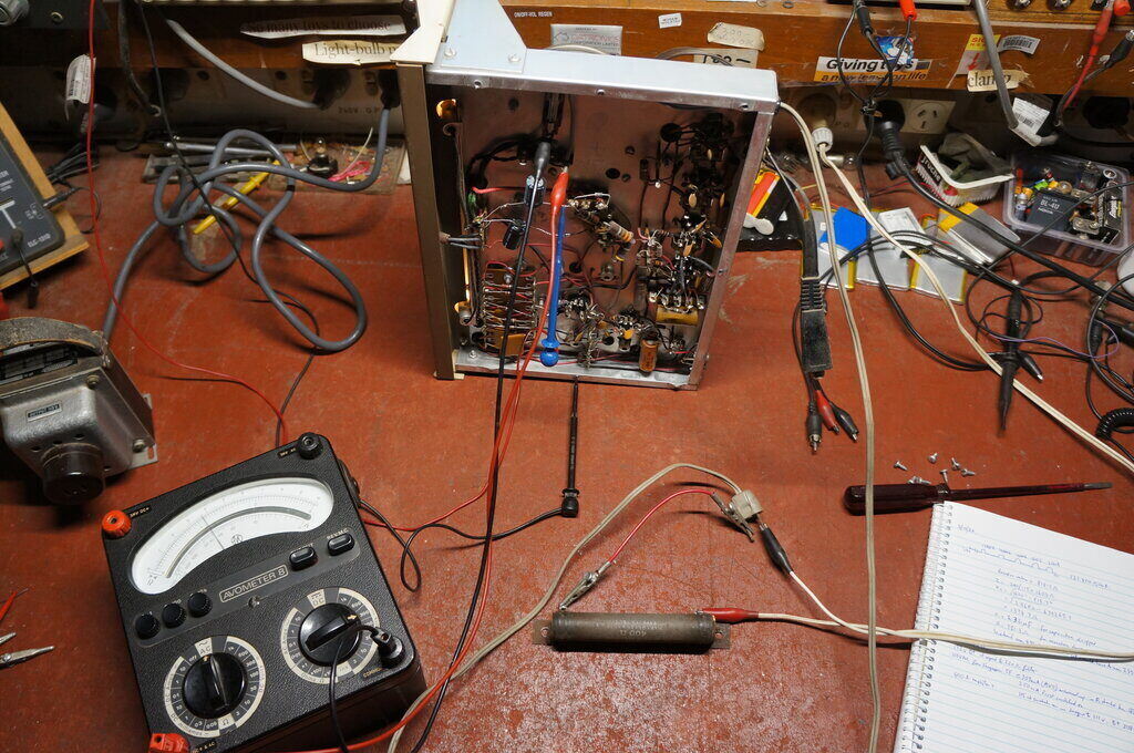
Measuring input voltage with the resistive dropper.
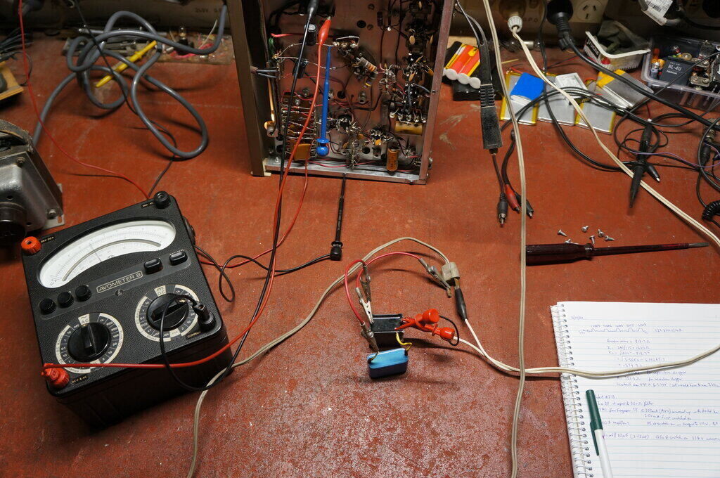
Now for the capacitive dropper.
The capacitor dropper gave a very gradual
rise to the input voltage at switch on. It took about 3 seconds for the
voltage to reach maximum as the heaters warmed up, and before the cathodes
warmed up. This point is defined as "AC at switch on" in the above table.
The resistor gave less voltage variation
than the capacitor (7V vs. 12V). Its disadvantage of course is the heat
dissipation is about 36W.
2. Sentinel AM/FM 315 Mantel Radio.
| Supply | Heaters max. voltage | AC after warm up |
| 600R resistor | 128 V | 120 V |
| 3.22uF capacitor | 132 V | 117 V |
This radio is further described here. It uses a typical 150mA heater string which adds up to 120.4V. For 240V operation of the heater circuit alone, the resistor value calculates to 797 ohms. Since the B+ current also flows through this resistor, the value has to be lower than this. The value is difficult to calculate since the B+ current is drawn on only every half cycle, because of the half wave rectifier. For the experiment, the resistor was started at 750 ohms and reduced until the radio received 120V after warm up. A so called "True rms" meter was used to measure the supply voltage to the radio. However, experience has shown this type of meter is not completely accurate on asymmetrical waveforms such as this. Nevertheless, the valve heaters looked about the right temperature, and the B+ appeared to be correct, since the FM tuning changes with large variations in B+ voltage.
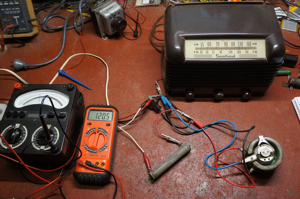
Testing with a dropper resistor. Rheostat is for adjustment.
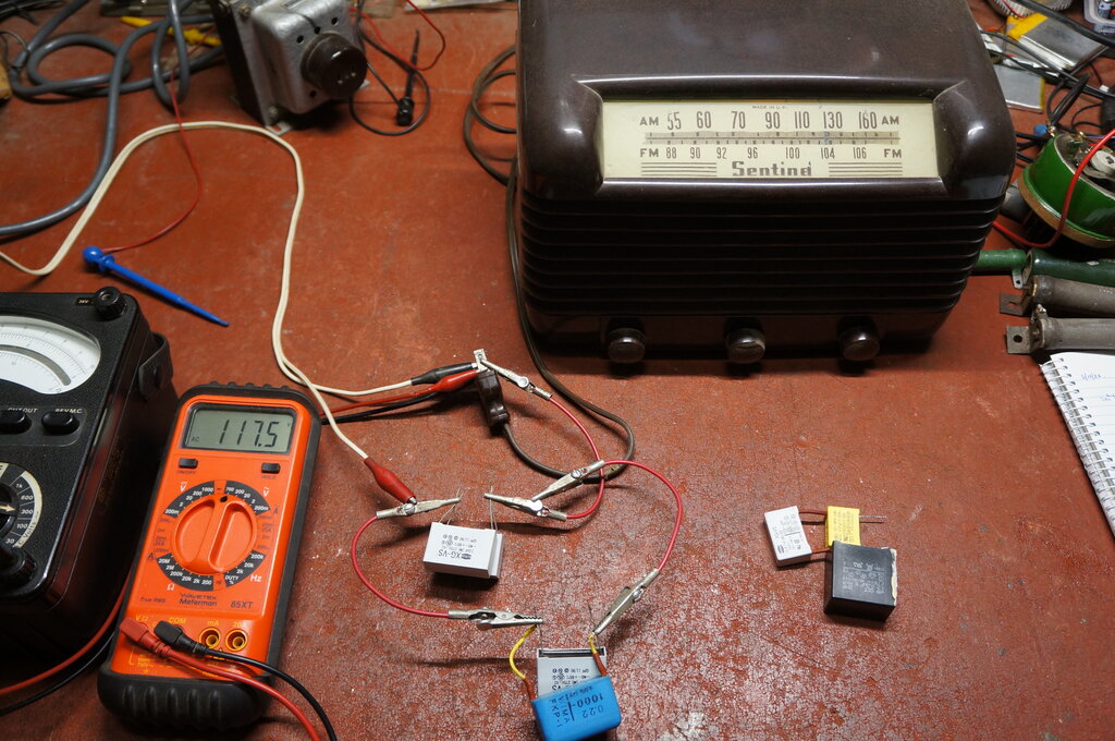
Sentinel with capacitive dropper.
I took this opportunity to view the current waveform, since the amount of DC added once the valves warmed up had me curious. It wasn't affecting the performance of the droppers to the extent I had expected.
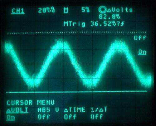
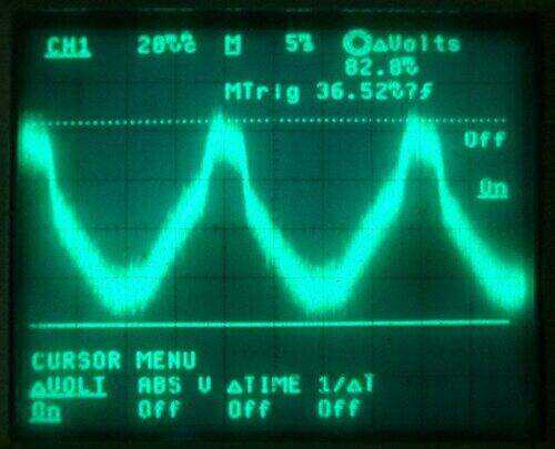
Current waveforms of the supply when fed from a transformer. At
left is the heater current alone, and at right is after the valves have
warmed up.
At left is the heaters only, before the
valves have warmed up. As expected, it's a normal sine wave. When the valves
have warmed up, the negative half cycle remains the same, but the positive
half cycle is distorted with an increase in current when the rectifier
conducts.
This is as was expected, although the
peak positive current was not as high as I thought it would be. Remember
that the rectifier plate conducts only for a very short time over the mains
cycle, so its effect on the total waveform rms is actually not as great
as first thought.
Looking at the waveform above, the positive
current peak is only about 4ms out of the full 20ms.
The circuit diagram for this radio shows an external line cord resistor to allow for 230V operation. The value quoted is 490 ohms, which seemed rather low. This was confirmed when I actually tried this value of resistor. At 120V input to the radio, the supply was 220V. Since this radio is also designed for DC, the choice of external line cord resistor becomes problematic. If the radio is run with the mains polarity reversed, no B+ current is drawn at all, and the heaters will receive excess voltage. As it is, on DC, a 490 ohm resistor assumes a total current of 224mA with 230V mains and 120V to the radio. Taking away 150mA for the heaters, this leaves a B+ current of 74mA, which seems a little high.
In terms of choosing between a capacitive and resistive dropper, the resistor provided less voltage variation; 8V for the resistor and 15V for the capacitor.
Conclusion.
The heater voltage variation during warm
up with both sets was a lot less than expected. Even though the heaters
did receive higher than normal voltage before the cathodes warmed up, it
is unlikely any damage would occur since, 1) the heater voltage rises more
slowly with a resistor or capacitor dropper, so the valve is never suddenly
'hit' with the higher voltage, and, 2) at this period of high heater voltage
no cathode current is being drawn.
It's tempting to simply install a series capacitor inside the Heathkit tuner, and twist the pins on the mains plug to fit the 240V socket, but would I? Probably not. For vintage equipment like the two sets used for the experiment, it detracts from originality, and besides, I've got more stepdown transformers than I can poke a stick at. Nevertheless, it has been shown to be practical (assuming the safety aspects are taken into account). On that note, the possibility of capacitor failure should be considered. Some kind of protection should be used if the capacitor short circuits. In the case of a transformer power supply, a fuse would probably be sufficient, since the transformer would saturate and draw excess current. Series heaters are a bit more difficult, since a fuse won't blow on its own. Perhaps a VDR across the heater string might work, or the Triac crowbar circuit shown elsewhere in this article. A more likely failure occurs with modern X2 capacitors, in that the capacitance drops over time that the capacitor is across the mains. In fact one of the capacitors used during the experiments had just this fault. Instead of being the rated 3.3uF, it measured 0.825uF.
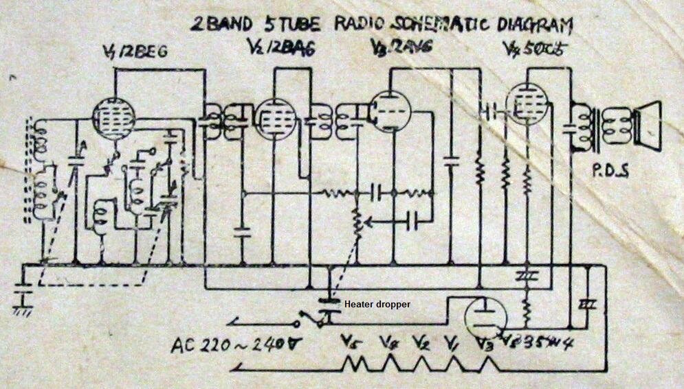
Japanese circuit for 220-240V.
It is a variant of the so called "All American
5", for use in 220-240V countries, but still using the 150mA U.S. series
heater valves. The circuit is quite ingenious, because the heaters never
receive excess voltage at any time during warm up, and the input to the
rectifier is fed with its correct 120V without any dropper. The following
simplified circuit will help understand it.
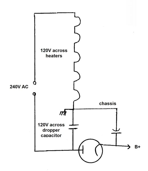
Simplified heater and rectifier circuit for 240V AA5.
Ignore the rectifier for the moment. Here
we see the heater string in series with a dropper capacitor. The circuit
is completely conventional at this point. Note that the heater string requires
120V, as is typical. This leaves 120V across the dropper capacitor. It
so happens that the AA5 circuit, with its 35W4 rectifier, expects 120V
on its plate to produce a B+ of about 150V. One could use a resistor to
drop the 240V to acheive this. But here they've cleverly used the 120V
across the dropper capacitor to feed the rectifier plate instead.
What they've done is to effectively connect
the heaters in series with the B+ supply, and since both require 120V,
this conveniently adds up to the 240V mains input.
Now for a closer analysis. The value of
dropper capacitor is less than would normally be calculated, since the
B+ current is also in series with the heaters. In other words, the B+ current
draw, plus the capacitor current needs to add up to 150mA rms. This means
the capacitor current is 150mA minus the rms value of the rectifier
plate current. The capacitor is chosen for 150mA rms heater current after
the valves have warmed up and B+ current is being drawn.
When the circuit is first switched on,
the heater current is therefore lower than normal, and the valve warm up
longer. But, once the cathodes begin to warm up, B+ current is drawn which
adds to the heater current, which then reaches the correct value.
In effect, the valves receive a softer
start than normal, and never receive more than 120V.
Because the heaters and B+ are in series,
the chassis cannot be connected to the mains neutral. It always floats
at 120V above earth regardless of mains polarity. Also, a short on the
B+ would overload the heaters, though not as drastically as if the dropper
capacitor shorted.
Again, anyone tempted to convert their
120V AA5 radio to 240V this way would be wise to check all the safety aspects
first. And as has already been mentioned, capacitive dropper circuits are
only suitable for the public mains supply, since this provides a sine wave
and can tolerate the low power factor.
When using a dropper resistor or capacitor to modify a 120V radio for 240V, it must be remembered that the insulation may be exposed to a higher voltage than it was initially designed for. In particular:
Many 120V series heater radios are not suited for modifying for 240V, because cabinet insulation is poor or non existant. This is a perfect example which should only be used on a double wound isolating transformer.
Be especially wary of various homemade designs presented in magazines, or on the internet, which are quite simply death traps in waiting. Some examples are shown here. Good commercially designed live chassis sets are perfectly safe as manufactured, but it's when the home constructor attempts to design something, that a dangerous situation can arise. It is often assumed that a polarised mains plug will guarantee the chassis is neutral (and thus at earth potentional), and safe to touch or connect to the outside world. Certainly, it helps but is in no way any kind of guarantee. The polarity of the mains socket is sometimes incorrect. Extension cords which might be used can also be wired with live and neutral reversed. Furthermore, even if the polarity is correct, if there is a break in the neutral, the chassis will rise to full supply voltage. The design must assume the chassis is always live. Many commercially made sets (particularly of U.S. design) switch the mains on the chassis side. This is actually poor design, because the chassis will be live one way or the other. With correct polarity the chassis will be at neutral when the switch is on, but when off, will rise up to full mains voltage. This is because the heater string completes the circuit between mains live and the chassis. With incorrect polarity, the chassis will be live when switched on, and at neutral when switched off. The best option is a double pole mains switch, or as second best, switching the live input. Certainly, if modifying such a set for 240V, the switch should be connected in the live supply instead, and if a double pole switch can be substituted, so much the better.
A deadly method which has been occasionally seen with home designed circuits is to connect the chassis to earth instead of neutral, and use the earth connection as the return path. Guarantees the chassis will be safe to touch doesn't it? Only if the wiring is 100% and stays that way. Consider a break in the earth connection in the set, or its power lead or plug. The chassis immediately rises up to full mains voltage. But, worse still is if the break in the earth connection happens to be further down the line, say at the fuse box. The set won't be the only thing live, but every other appliance on that circuit after the break in the earth connection. Incidentally, using the earth as a return path for AC mains is generally against regulations.
Particularly prevelant around the internet are battery eliminator circuits using a capacitive dropper and bridge rectifier; designed to run low voltage solid state circuits, or perhaps charge a battery. The disappointing thing is the designer can't see how lethal their design is, and presents their designs as projects for inexperienced constructors.
