From time to time, really bad examples of design are seen. This is a new section of the site to draw attention to such things, and may include magazine projects, things seen on the internet, and commercially made designs.
1. "Television" magazine's colour
TV project.
Spread over issues from 1972 to 1973,
was a series of articles on how to build your own colour TV. The article
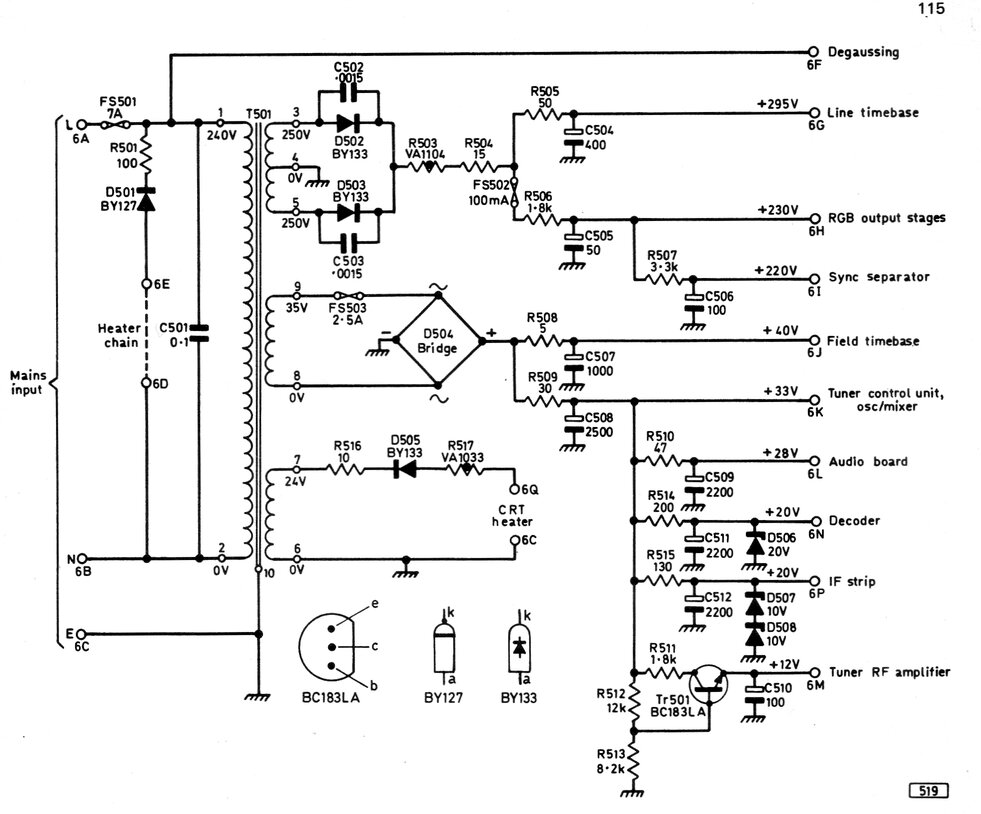
which drew attention was Part 10; the power supply, described in January
1972.
Alarm bells rang when I read the description of the heater circuits for the valves and CRT. Let's look first at the valves, and see where the designer has gone horribly wrong:
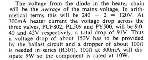
Wrong! The voltage from the diode dropper is not the average at all. As we have seen from the detailed analysis in the diode dropper article here, the voltage will be 170V rms, when the supply is 240V. The introduction of the diode halves the power, not the voltage. Looking at the heater string, there are three valves in series which require 91V at 300mA. With the diode in circuit, and our supply now 170V rms, the resistor should be (170 - 91) / 0.3 = 263 ohms. A far cry from the 100 ohms specified! For the 100 ohm resistor to be correct, the heater string would have to add up to 210V. Incidentally, the correct 263 ohm resistor will dissipate 24W. Turning next to the CRT, the designer has made just as much of a blunder:
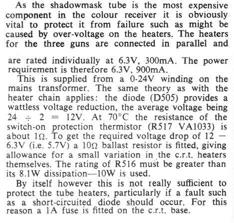
We have a 24V transformer secondary which
is to feed the 6.3V 900mA CRT heater. Why a 6.3V winding was not specified
is just bizarre. Instead, the designer has worked out ways to get rid of
the excess voltage with a diode, a thermistor, and a resistor. A fuse is
erroneously included in case the diode shorts. So much extra work (and
inefficiency) when a simple 6.3V winding would have avoided all this. Now
to the calculations:
24V AC fed into a diode dropper will result
in 17V rms output; not 12V. The 1 ohm thermistor will drop
900mV, which means a total of 7.2V needs to be supplied to the CRT + thermistor.
With 17V rms to start with, the dropping resistor should be (17-7.2) /
0.9 = 10.9 ohms.
This is actually close enough to that
specified, so in this instance the CRT will be OK, although maybe just
a fraction over-run, depending on the actual heater current. However, the
designer's calculation to get to this value is incorrect. 900mA will result
in 9.9V drop across the 11 ohms, consisting of the thermistor and 10 ohm
resistor. 9.9V + 6.3 = 16.2, not the 12V assumed. He's got the power rating
of the resistor right though.
Colour CRT heaters are not designed for series heater use, so there may be some slight variation in current, and the resistor should really be selected on test. The fuse to protect the heater in case of the diode shorting won't do much good. The maximum short circuit current with just the 11 ohms of resistance in circuit will be 2.18A. A 1A fuse will certainly not blow immediately. But, the current with the CRT heater in circuit will be quite a lot less than this, and it could be hours before the fuse blows. "What a nice bright picture!" exclaim the viewers, as the CRT heater is being fed something closer to 12V, happily stripping the cathodes. Why didn't the designer just put a reverse biassed shunt diode across the heaters to protect them?
On to the other interesting features of this power supply:
An example: A 12R resistor is connected
across a 12V supply. It draws 1A and the power is 12W. These values are
the same for DC or AC rms.
Now, our designer thinks that if the power
across the resistor was halved, so would its voltage. So, for 6W dissipation,
what will the voltage across the 12R resistor be? (The designer would think
6V, but we'll see in a moment that is not correct).
P = V^2 / R. Therefore, 6 = V^2 / 12.
This means that V^2 = 72. The square root
of 72, and thus V, is 8.49V.
We see that the voltage is not
halved at all!
And guess what? 8.49 / 12 = 0.707. If you remember from the diode dropper article, you will recall that the voltage fed into the heater chain was 0.707 times the supply voltage. Here, I've arrived at the same figure, but by a different means.
Put simply, the mistake is in assuming a linear relationship between power dissipation and voltage. He's forgotten all about I^2 x R. Power dissipation vs. voltage is not linear.
As an example of how to do it correctly, have a look at the calculations for the Thorn R2M television. A set made in the thousands by a reputable manufacturer. And the valve heaters all work at the correct voltage!
There's just one more little mistake to wrap up his analysis of the heater string. Regarding the drop across the heater rectifier diode; "about 0.1V at 300mA". Oh dear...not terribly brushed up on the characteristics of silicon diodes are we? Fortunately, whether it is 0.1V or 0.7V will have no practical effect in this application, but just that statement shows a lack of knowledge.
Also mentioned was the CRT heater supply. He did admit the 1A fuse was futile by saying, "This was dropped because of favourable operation without it". But his 10R heater resistor was justified on the basis that the mains voltage might be 10% high, and the tolerance of the mains transformer might also be of 10% tolerance, thus "the transformer might rise to 29V instead of 24V". He actually thinks the CRT heater is being underrun "in order to offer some protection". Actually, under running the heater on a CRT is more detrimental, due to cathode poisoning, to say nothing of reduced cathode emission. Does he think the heaters will burn out? Well, actually heaters of indirectly heated valves are quite forgiving of excess voltage. Take car radio valves for example; operating on closer to 7V than 6.3V. No, the CRT heaters aren't going to go open circuit with normal mains and transformer voltage variation. Think of CRT brighteners; it's not the heater burning out that eventually kills the tube, but no emissive left coating on the cathode. However, with all that said, it was just fortuitous that his erroneous theory did end up with close to the correct operating conditions, although ironically, slightly overrun!
Correction at last.
In August 1973, (20 months since the circuit
was first published) we finally see the designer has realised the error;
or more likely, notification of the error continued to come in, and notice
had to be taken. Perhaps some readers were disturbed by valves glowing
like light bulbs. In the last sentence for the article on the receiver
project, it simply reads; "The correct specification for R501
is 260 ohms 25W".
Then in September 1973, readers are reminded
again of the correction, and this time an RS components part is specified.
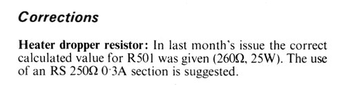
However, there's still no word on the error of the original calculation.
The matter is finally put to rest in April 1974, with an article titled, "The Diode Dropper". This went into the calculations in some detail, and somewhat coincidentally, the colour TV project was used as an example. It's quite likely that the author was one of those who questioned the original design.
2. Headphones Connected to the Mains.
For many years, circuits have been shown
in magazines and on internet sites of radio receivers using a transformerless
power supply for the B+. What the designers appear to be unable to understand
is the lethal earphone/headphone connections.
This example was from a Japanese site and shows a one valve VHF receiver. While some of the design aspects are questionable, the important point here is that the crystal earphone is connected directly to the chassis, which in turn connects to the 100V power mains via the bridge rectifier. The earphone will always be live, regardless of how the mains plug is inserted.
Earphone live at 100V AC.
The book, "Radio for the Millions", is a compilation of projects which have appeared in Popular Science. This publication presents a pot-pourri of deadly circuits, typical of those often described in U.S. magazines. The following is a typical example:
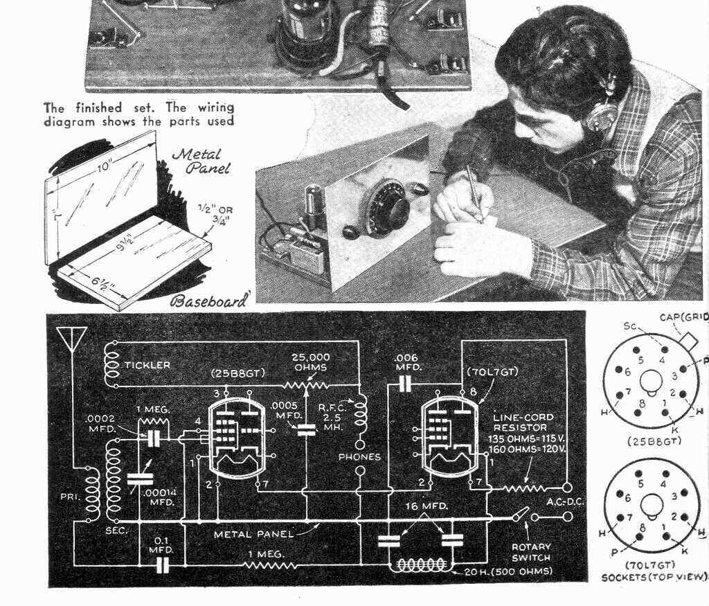
Would you be comfortable with 120V on your head, let alone
the front panel?
In this set, we see the aerial connected to the 110-120V power mains with no isolation. Furthermore, the metal panel which forms the front of the set is connected directly to the mains. The headphones connect straight to the B+, which in turn connects to the mains supply via a half wave rectifier. Regardless of which way the mains connected, the headphones will always be connected to the mains, either through the rectifier, or the 25B8 pentode. More than enough lethal current can flow by either of these paths.
3. Non-isolated Power Supplies.
Also from "Radio for the Millions", this
circuit invites the constructor to connect their portable radio to the
mains without any isolation.
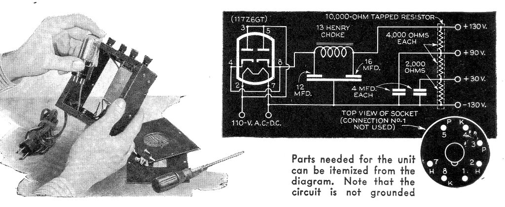
What of the external aerial connection
that the radio might have, exposed screws, or other metallic parts connected
to the chassis?
Looked nice, but not a good design.
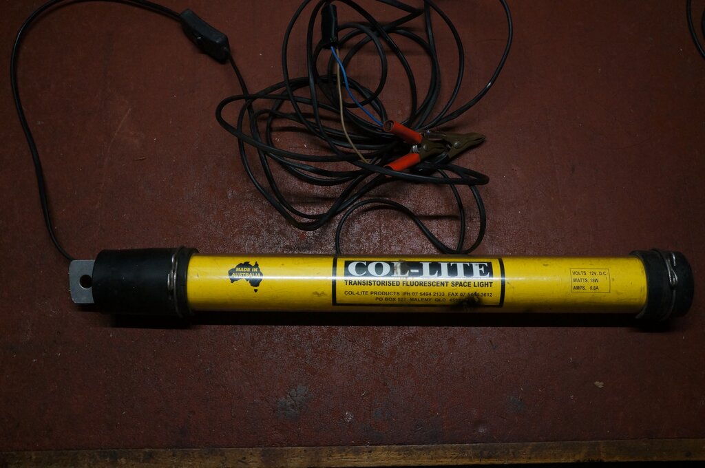
This 12V 15W fluorescent light was bought at a swap meet. It's the type of thing often sold for working on cars. The fluorescent tube is contained in a clear plastic tube fitted with rubber end caps, and the supply cable emerges from one of these. Some sort of hook is usually provided to hang the lamp. The "Col-Lite" website is no longer extant, but searching through the "wayback machine" did bring up some old pages. Apparently, the lamps sold for $100 new. They were assembled in what might be described as a cottage industry. I gather production ceased because of fluorescent tubes becoming obsolete and difficult to get (especially the 15W type used here), and that the owner was getting too old. It appears production started in 1980.
Alas, the lamp was inoperative, drawing no current from a 12V supply. It transpired that a previous owner had reversed the battery clips. The supply cable is 240V double insulated mains cable with brown and blue conductors. Near the lamp is an inline switch. I thought it odd the brown wire was connected to the black clip, and the blue wire to the red clip. Sure enough, reversing the connections did restore operation - for a while. The severely blackened tube end was the ominous sign of a tube run from a single transistor inverter, with no cathode heating. This is typical of so many battery operated fluorescent lamps. The designers don't know or don't care. The tube lights up long enough to sell the product, but then the user notices the tube life much shorter than a tube run from the mains. The more often the tube is started, the more its life is shortened. And, as is often the case, the tube is run at much less current than it should be - hence the 'dimmer than the mains' characteristic. In this instance, the current is quoted at 800mA at 12V. That's 9.6W. With inverter efficiency taken into account, the tube is running with not much more than half its rated power.
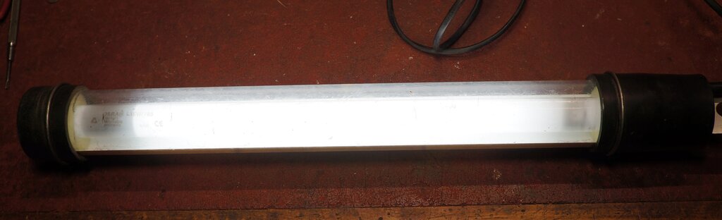
Tube life is short because of improper operating conditions. Note
the severely blackened end.
The proper way to operate a fluorescent
tube is to heat the cathodes when starting, and to preferably run the tube
from a symmetrical waveform. Indeed, looking at the waveform did reveal
the "Col-Lite" uses a one transistor inverter, which creates a DC component
across the tube. Photos of the manufacturing process from an obsolete Facebook
page confirmed this. A TO-3 transistor (probably a 2N3055) drives a ferrite
pot core transformer.
Not surprisingly, only single wires were
connected to each end of the tube. A great way to strip the cathodes when
starting the tube! Incidentally, it is often possible to get a bit more
tube life from these simple inverters by reversing the tube. The end of
the tube which has blackened and lost its emission, will sometimes work
reasonably well as an anode. When this lamp was initially powered up, the
tube provided a dim glow, obviously not starting. In fact it was so worn
that the heater at the blackened end was open circuit. Luckily, I was able
to get away with reversing the tube, and as can be seen from the above
photo, it now works quite well - for a bit longer.
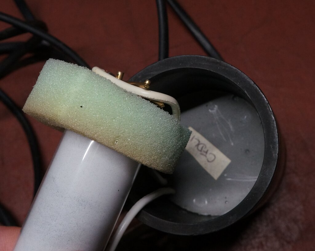
Inverter potted in epoxy. Note single wires to each end of the tube
- there's no cathode heating.
But the worst aspect of the design is that
the inverter is sealed in potting compound. The inline switch is also sealed,
but that's a minor issue, since it can easily be replaced. The lamp operated
some of the time I had it powered up. Assuming the inverter or the switch
might have an intermittent fault, I had to destroy the switch to find out
this wasn't the problem. It was actually invisible damage inside the cable.
Once this was repaired, the lamp worked all the time. But what if the inverter
had been at fault?
First hurdle would be to actually extract
the potted inverter from the rubber end cap. Then either chip away or dissolve
the potting compound to access the components.
It's pretty pathetic really - it's not
as if a one transistor inverter to drive a fluorescent tube is a secret
design, and the component values must be hidden from curious eyes. Besides,
you'd be a fool to copy the electrical design used here, to create a competing
product. What does the manufacturer expect us to do when the inverter fails,
or the supply cable needs replacing? Buy a new (expensive) lamp? All I
can say is, I'm glad I didn't pay full price for this one!
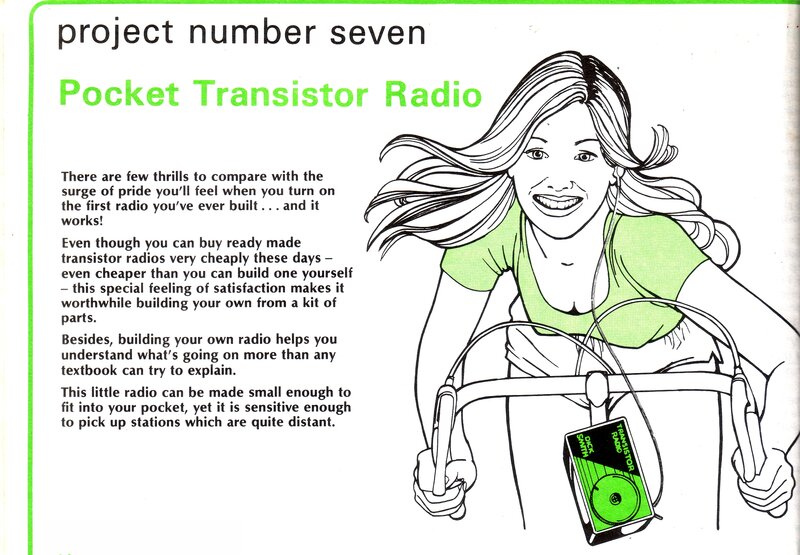
This project is especially memorable, since
I was caught out by its poor design. At the time, back in 1981, I did not
have the understanding to put it right, and it remained unused for some
time, until I realised just what the problem was. Upon constructing the
set, it suffered from instability, and no adjustment of RV1 helped.
The radio in question has been described
in the ZN414 article
here. As explained, the ZN414 is designed for a nominal 1.5V power
supply. This voltage is actually quite critical, and good ZN414 circuits
will have some method of adjustment, to suit the individual operating conditions.
At its simplest, this is is a variable resistor in series with the supply
of the ZN414. Incorrect voltage will result in poor gain and selectivity,
or instability. The control should be user adjustable, since the performance
of the IC varies across the band.
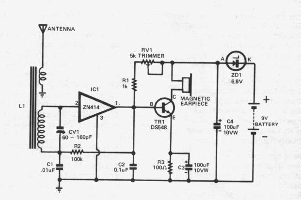
The design fault here is how this "1.5V" was obtained. As explained in the construction article, a 1.5V cell was not used, because it was considered "difficult to solder" to the terminals, and a battery holder would not fit into the small case used. This series of projects was designed in 1980, before the prolific appearance of AAA cells, and the availability of battery holders to suit. Back then, the smallest commonly available cell was the AA size. So what did the designer do? Well, at first glance it's quite ingenious. Practically, it suffers from one major problem.
The smallest battery that would fit the box was the 9V 216 type. How to get "1.5V"? Simply connecting a zener diode in series was the answer. Here we see a 6.8V zener in series with the 9V battery. Connected in the direction shown, the zener is reverse biassed, and thus drops 6.8V. The result is 2.2V at the anode end of the diode. It's more than the 1.5V required, but we hope there's enough adjustment in RV1 (there wasn't in my set - hence the instability). With a 9V supply, a 7.5V zener would have been a better choice. But, aside from that, the real problem is as the battery ages, and the voltage drops.
Generally, we might consider a 1.5V cell
exhausted at around 1.1V, and good designs will operate down to this figure.
For a 9V battery, this equates to 6.6V. Have you spotted the problem yet?
Let's look at what happens to the battery voltage, and the supply to the
ZN414 as the voltage falls:
| Individual Cell Voltage | 9V Battery Voltage | ZN414 Supply Voltage |
| 1.5 | 9 | 2.2 |
| 1.4 | 8.4 | 1.6 |
| 1.3 | 7.8 | 1 |
| 1.2 | 7.2 | 0.4 |
| 1.1 | 6.6 | 0 |
| 1.0 | 6 | 0 |
We can see that the radio will be largely
inoperative with the battery voltage falling to only 7.8V. At this voltage,
the individual cells of the battery are 1.3V, which is quite sufficient
within the realms of adjusting RV1, to provide good perfomance. In fact,
the ZN414 was actually designed to be operated with a 1.3V mercury cell.
By the time the battery has fallen to 7.2V, there's not even enough voltage
to bias the PN junctions in the ZN414, and it becomes completely inoperative.
Yet, the cell voltage is 1.2V.
The result is very short life of the 9V
batteries used. Added to this, is that as the project was presented, RV1
was a preset adjustment inside the case. It would actually need frequent
readjustment in this configuration.
It should be obvious now, that the individual
cells inside the 9V battery would be capable of operating the radio, long
after they had ceased to do so with the zener diode dropper.
Bad design doesn't end there. It's also extremely wasteful of the battery, because most of the current drawn by the radio is wasted in heat across the zener diode. Only one sixth of the battery power actually operates the radio. Given the high cost of 9V batteries, it's a significant expense to operate the radio this way. Effectively, you're paying for six cells, but can only use one - and then only for a much shorter time, than if it was used directly. Having analysed the circuit thus, one other point was overlooked by the designer. The audio output stage could have been operated directly from the 9V supply, with an increase in output. Furthermore, by switching to a crystal earphone, the current consumption would have been reduced considerably.
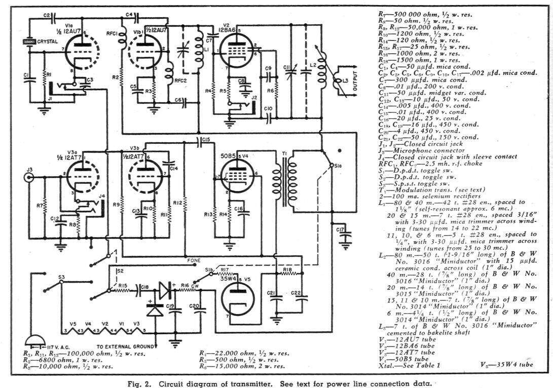
The designer thought he had solved the
problem of live chassis equipment once and for all. The idea was to earth
the chassis/cabinet directly to a "good external ground", and provide only
the live connection from the mains. This meant that regardless of plug
polarity, the metalwork, and microphone or Morse key, could never become
live.
Note in the circuit, the mains cable is
only one wire, connected to one of the plug pins. Provided the pin connected
to the transmitter is connected to the live connection of the socket, the
transmitter will function, with the supply return being through the earth.
As is well known of course, the mains neutral is also earthed, so a return
path exists.
If the plug is reversed, the metalwork
is still at earth potential, thanks to the "good external ground", but
of course the transmitter won't function, since there is minimal voltage
difference between earth and the neutral connection of the power point.
In a 'normal' live chassis circuit, if an external earth was connected to the B- or non isolated chassis, and the plug was inserted with wrong polarity, the live would be shorted to earth, with the usual blown fuse or tripped breaker. This circuit avoids that by not having a neutral connection; instead relying entirely on the external earth connection as the return path.
It's a great idea - in theory! But, here's
where the scheme comes unstuck: The whole thing relies on that "good external
ground". What is defined as "good" is not explained. A pipe driven into
the ground can actually have quite a high resistance, in the region of
hundreds of ohms. This will depend on the length and area of the earth
connection, and the soil characteristics and its moisture content. With
a mains supply of only 117V, a serious loss of voltage is likely to occur.
Not only will the transmitter function poorly, or not at all, but the metalwork
will be live above earth by that voltage drop. A shock hazard starts to
exist.
Now, if the user has used the same water
pipe to which the house electrical system is earthed, everything will function
correctly, with full mains voltage presented to the transmitter power supply,
and the metalwork will present no shock hazard.
However, the ultimate downfall of the
scheme is, what if the earth connection is disconnected or otherwise faulty?
Well, the chassis, cabinet, Morse key, and microphone will be guaranteed
to be live at 117V!
The designer states in the article, "this
ground connection must be made before the plug is inserted into
the receptacle". All well and good for the warning, but it's all too easy
not to be thinking and connect the mains and earth in the wrong order,
or even forget the earth is not connected before plugging in. What about
someone not familiar with the equipment?
Incidentally, most supply authorites forbid
the use of the earth connection in this manner, for the reasons described.