The Baird brand was used by Radio Rentals. The sets were made by Thorn.
The Baird brand was used by Radio Rentals. The sets were made by
Thorn.
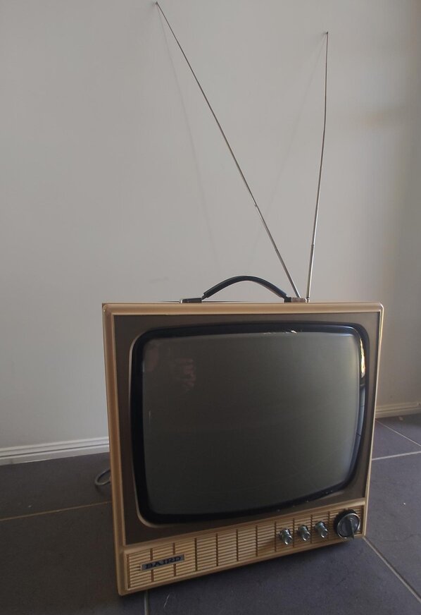
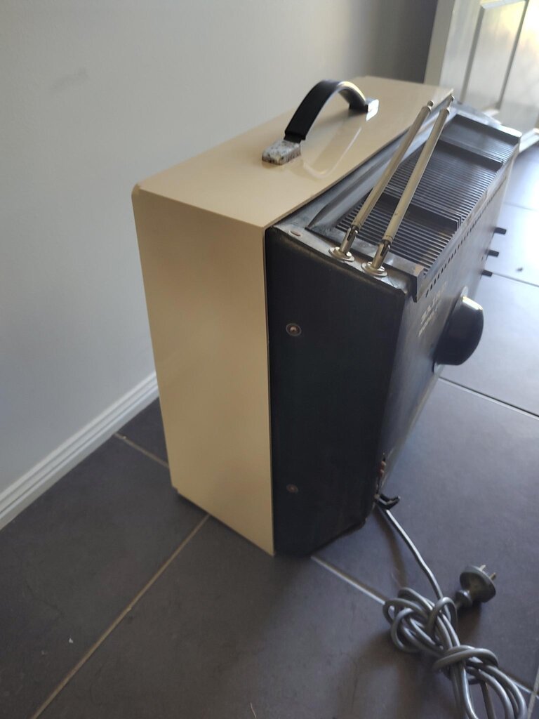
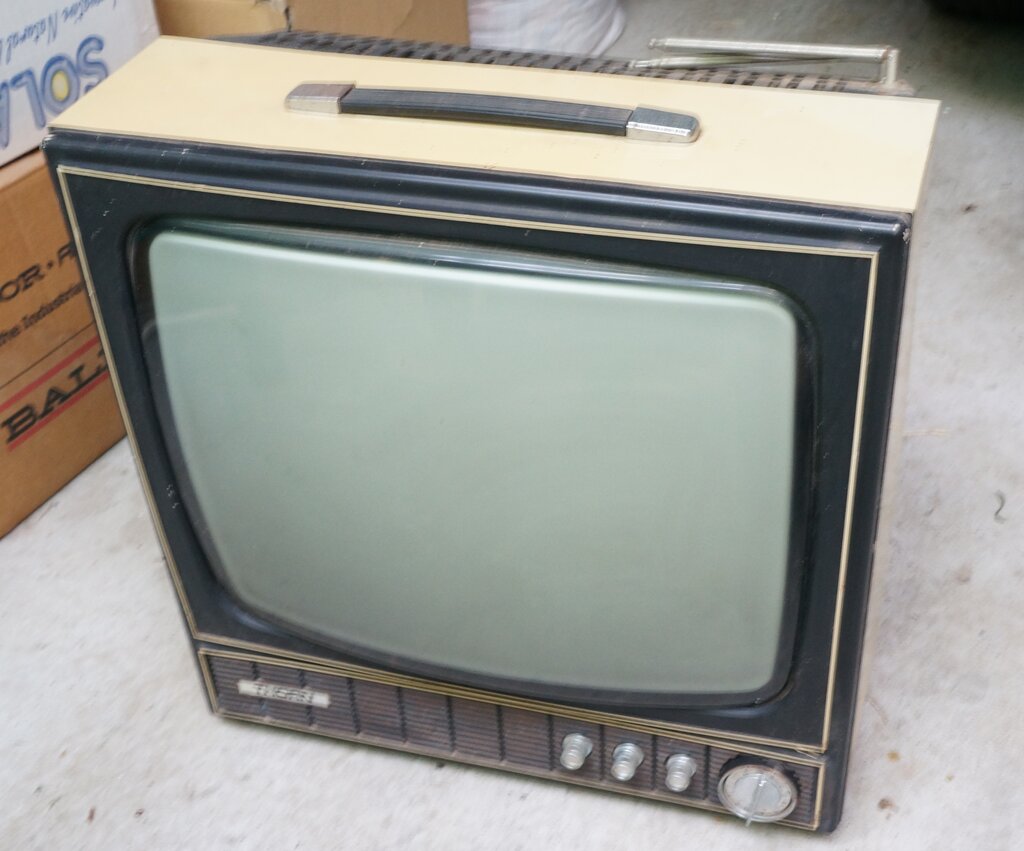
The Baird 808 is another of the Thorn R2M
chassis sets. It is a 17" portable which was supplied by Radio Rentals.
A later version of this set is the 811, which appears to have been for
sale, rather than rental only. The 811 has a minor cabinet restyle, and
the cabinet back is ruggedised at the top, since the original fibreboard
deteriorates from the heat produced by the dropper resistor.
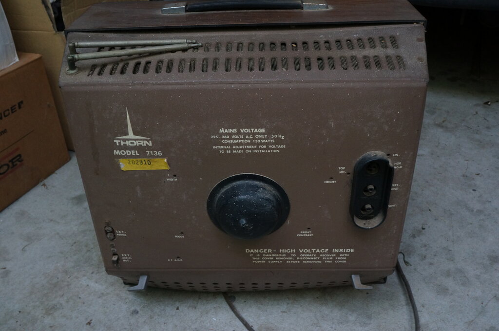
There are two other sets in this series
of almost identical appearance. Both use a transformer isolated power supply.
One has a similar beige cabinet as the 808 and 811, and the other has a
wood grain finish. Both are branded Thorn. The wood grain cabinet model
is 7136.
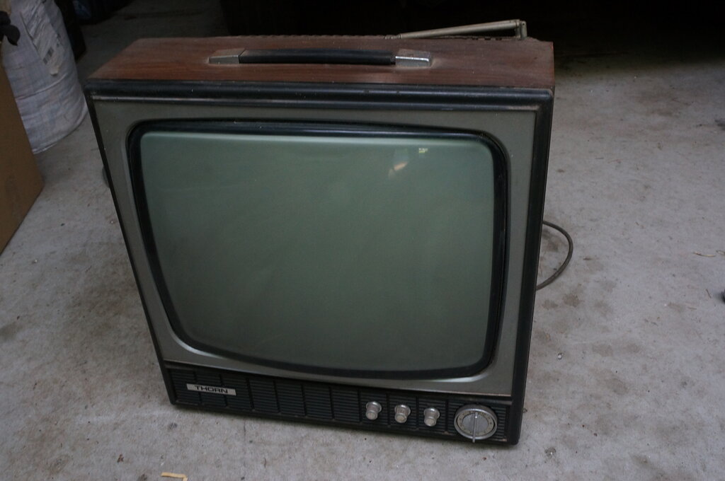
The set described here is one of the Radio Rentals "Baird" branded sets with the 808 model designation. It was made in 1972. The Thorn R chassis has been described previously, so this article is more about the restoration of an 808. The notes are also applicable to the 811. With the exception of the power supplies, the notes are also applicable to the R1 and R2 chassis.
I acquired this set from another HRSA member, something like 20 years ago. I had another one of these previously, which I'd foolishly given away to another collector. With the constant mention of the Thorn 1500 chassis in "Television" magazine I'd been reading of late, I was motivated to finally restore this one - which definitely won't be given away!
Brief History of the Thorn R.
In 1969, Thorn in the UK released their
first single standard 625 line hybrid chassis, the 1500. This became one
of the most popular and reliable sets throughout the 1970's. Construction
is almost entirely on one printed circuit board, mounted vertically on
swing out hinges.
Service access is excellent. Thorn and
AWA adopted the design in Australia in 1970. Thorn designated it the "R"
series, and AWA, the "58" series. However, the Australian version is not
an exact copy. While the layout is the same, and a lot of the circuit is
identical, there were differences to suit Australian conditions and components.
There are three versions of the R series; R1 is transformer powered
with 6.3V heaters, R2 is transformer powered with series heaters,
and R2M is series heater with no transformer. Some servicing literature
depicts the R2 as "R-11", which could be because the 11 is meant to be
the Roman numerals for 2.
At this point, I recommend reading the
Baird 812 article to learn about the R series, so that this article makes
sense. The technical design is covered in that article.
Thorn R2M Circuit.
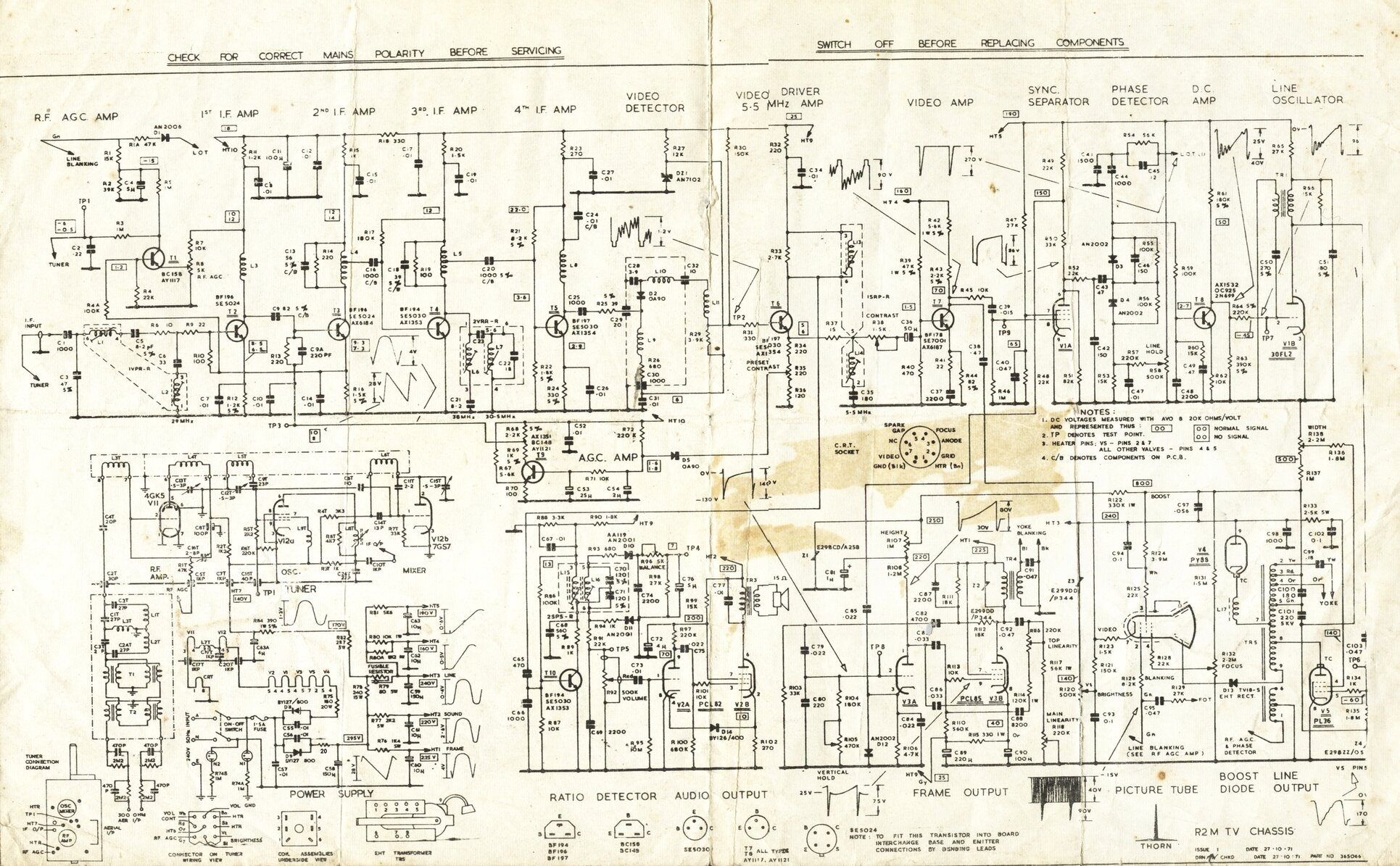
Right click and view externally for full size.
The circuit is provided here for reference to the specific points brought up in the following description of the restoration. Note that the original circuit as printed has some mistakes in the power supply circuit. The heater dropper diode is shown as reversed, and the 20 ohm anti-surge resistor is not shown. The diagram shown above has been corrected. Incidentally, the R2M circuit is not shown in the JR service manuals, which suggests this model was exclusive to Radio Rentals, intended to be serviced only by them.
Restoration Begins.
The most obvious thing to begin with was
the mains cable which had been cut off. I had temporarily tried the set
when I first got it, but can't remember what the results were. I had noted
at the time the 20 ohm anti-surge resistor had been replaced, and this
resistor was now open circuit. I'd left a 20R 20W resistor sitting inside
the cabinet for when I got around to the restoration. Like all of the R2M
chassis I've so far seen, the 180 ohm dropper resistor (R75) was open circuit
and had been replaced. The set was otherwise complete and original as far
as I could tell, except it looked as though the PCL85 and PL36 valves had
been replaced. Not surprisingly, both telescopic aerials had been broken
off.
The first thing to do was to replace the
mains cable. I found something of the same diameter, and with the old red/black/green
conductors to match the original. Even though this is a live chassis set,
the earth is used for two things: 1) to operate the polarity neons, and,
2) to protect the earphone socket from speaker transformer breakdown. The
polarity neons simply indicate whether the chassis is live or not. It's
an excellent safety feature which I've never seen in any other live chassis
set. If the chassis is live, the polarity can be reversed by swapping the
mains connections between the power switch and PCB. There's connectors
in the supply lead for this purpose. Of course, this precaution is irrelevant
where an isolating transformer is available.
The live and neutral conductors of the
mains cable are terminated directly to the double pole mains switch. Since
this is of plastic construction, it's unwise to desolder the old connections.
The switch contacts will loosen up and shift position. I learned this from
my first R series chassis! My preferred method is to cut the old conductors
away from the switch by, say, 60mm, and then join the new conductors, covering
with heatshrink tubing. The earth connects to a terminal block, so this
precaution is not necessary for that conductor.
At this point, I was ready to try it and see what happened. Apart from the 'safe' polarity neon and the valve heaters lighting, nothing else came to life. There was no B+, and then I was reminded why I'd left the 20 ohm resistor in the set. With it attached by clip leads, there was brief signs of line deflection, but no frame deflection or sound. The horizontal line was randomly varying in width. It wasn't very bright either.
Capacitors.
None of this was any surprise of course,
but I just wanted to satisfy my curiosity. The weak point with these sets
now is the AEE Miniprint metalised paper capacitors. Back in 1972 they
were reasonably reliable, but over time the epoxy cracks, which of course
admits moisture and thus causes leakage.
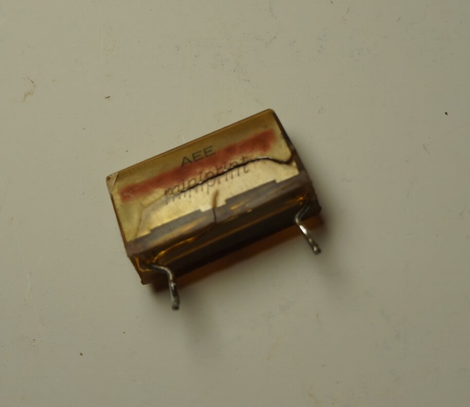
These AEE Miniprint capacitors have deteriorated and should all
be replaced as a matter of course. This particular capacitor is C99 - the
0.18uF S-correction capacitor.
Some time in the past, a few of these capacitors
had been replaced around the frame oscillator and output stage, with the
Philips axial polyester type. There was of course no need to replace those.
Other than that, the non-polarised capacitors in these sets are polyester
'greencaps' and disc ceramics. These are generally reliable enough not
to worry about. The set is also young enough that the electrolytic capacitors
should still be OK.
Once all the AEE Miniprints had been replaced,
I powered up again. This time we had proper line deflection, but still
no frame deflection or sound.
No Frame Deflection.
The PCL85/18GV8 frame oscillator valve
appeared OK, since the 25V supply for the solid state front end comes from
its cathode. This was present, since changing channels caused a disturbance
in the horizontal line. Rocking the valve in its socket, so the pins made
and broke contact, should have caused some vertical displacement, but it
didn't. The frame output transformer primary was obviously OK, since there
was plate voltage for the PCL85. What about the deflection coils? Connecting
a DC power supply across those should cause a shift in the position of
the horizontal line, except it didn't. Removed from the set and tested,
there was clearly an open circuit. There's two sets of coils; one for the
upper deflection, and another for the lower. They're connected in series,
and then in series with a thermistor, which compensates for the resistance
change in the windings as the coils warm up. This was OK, but one of the
coils wasn't. A close look revealed a likely cause - the ubiquitous brown
glue. Sure enough, pulling on the wire where it went under the brown glue
caused it to come free. Fault confirmed!
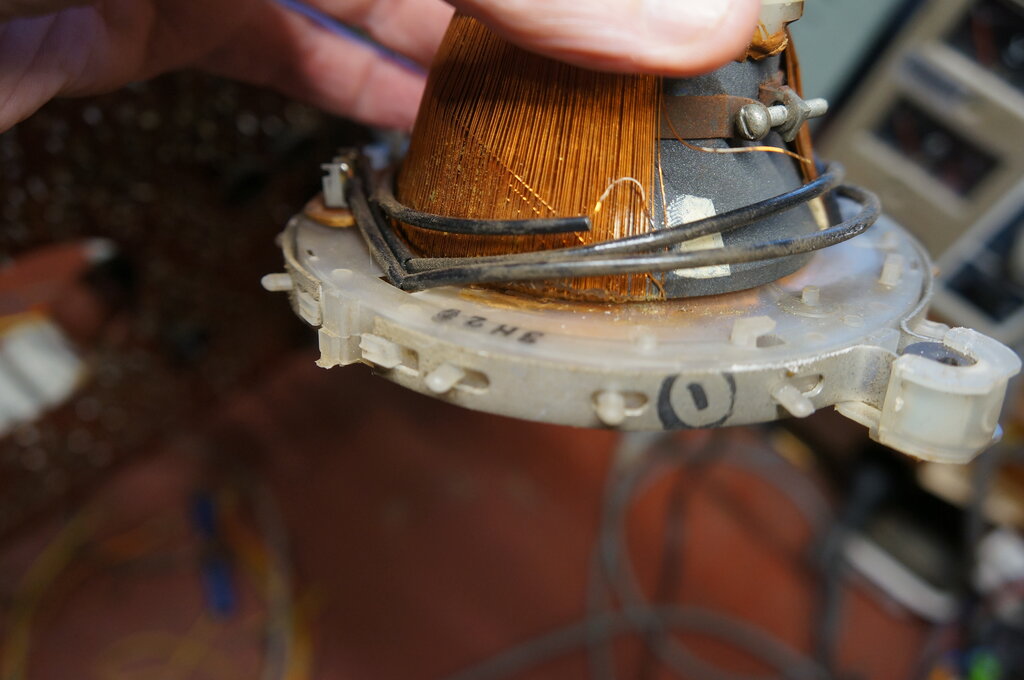
I'd scraped away most of the brown glue before taking the photo,
but its location is visible between the plastic and copper wire.
I tried bypassing the corroded section, but the result wasn't satisfactory at all. It was difficult to know which part of the winding to bypass without dismantling the whole thing. The yoke used in many of the R series, including this one, is a Plessey/Rola TV7000. Otherwise a Philips yoke is (not surprisingly) used, since the line output transformer is Philips. Since I have a few spares, it was easy enough just replace it. Now we had full deflection. The yoke I used was a Japanese equivalent, marked DOK 360023. Originally, these sets use a Thorn invention; the "linearity sleeve". It's a thin piece of paper to which is bonded a copper strip in the form of a shorted turn. This slips in between the yoke and CRT neck, and is used to adjust the line linearity. How far forward or back the shorted turn is, relative to the horizontal yoke windings, determines the linearity. As it happened, the linearity with the new yoke was good enough not to require the linearity sleeve. I did try it to compare, but there was no real discernable difference. Also, by virtue of the shorted turn, it takes some energy from the line output stage, as was evident with a slight reduction in width when it was inserted. Obviously, it's better for the line output valve and line output transformer to have the least necessary loading.
Linearity sleeve. Not required with the replacement yoke.
No Sound.
The PCL82/16A8 audio valve was passing
current, as evident by voltage across the 270 ohm cathode resistor (R102),
but there wasn't the slightest hum or other sound in the speaker. Often
this is because of oxidised connections in the earphone socket. That is,
unless the set was made in the 1970's, and has a Magnavox speaker - just
like this one. Plugging in headphones did provide sound, and testing the
continuity of the speaker voice coil showed it to be open circuit. In the
current day, I am finding more of these speakers open circuit than not.
The Thorn S series portables also suffer notoriously, and it was one of
these when I first encountered the problem. It seems the glue which secures
the wires to the cone paper reacts with the copper. In some instances it's
possible to bridge out the open circuit section, and this time I was lucky.
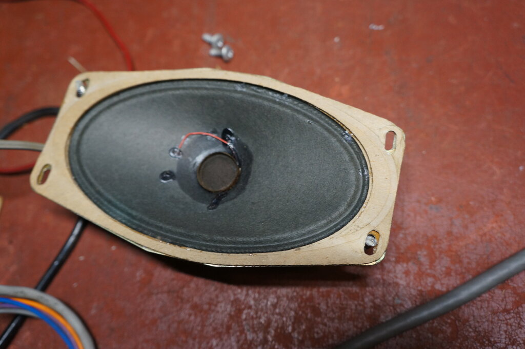
Open circuit section bridged.
Unfortunately, in some instances the corrosion
occurs further into the voice coil where it's not easily accessible. (I've
got a Thorn S series waiting for another speaker). And, to make things
more difficult, the speakers fitted to these Thorn sets are not of a standard
size. This is most likely because the cabinets use the same mouldings as
the British sets. One way around this is to make up an adaptor plate out
of plastic or aluminium, so as to use something more easily available with
the original mounting holes.
Anyway, in this instance, sound was restored
with minimal work to the speaker. I used a thin piece of wire wrap wire
to bridge the open circuit, and secured it with contact cement. Some distortion
was evident, and this turned out to be warpage of the speaker frame. This
is not an uncommon problem, particularly with small speakers, with their
small voice coil gap. I found placing a piece of cardboard under one corner
before it was screwed down helped. I really would like a new supply of
speakers with the same mounting holes!
Not all Channels.
Normally, there should be snow on all
channels when there's no signal. Except here, channels 3,4, and 5 provided
a blank raster with no snow. Since I can transmit on all channels with
the M69 modulator, I tested the ability to actually receive on the faulty
channels. Alas, there was barely something in the background. And the tuner
was obviously working to some degree, since adjusting the fine tuning changed
a slight herringbone pattern which was visible. It seemed something might
be oscillating.
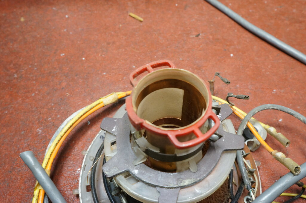
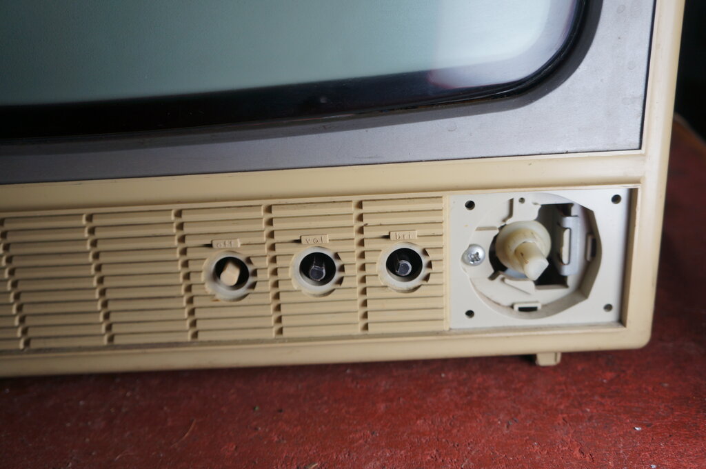
Since the tuner may have dirty contacts
after all these years, I decided to extract it and see. How to get the
tuner out is not obvious at first. The small panel with the three controls
(power, volume, brightness) has to be removed first. It's secured with
two screws.
Next, the channel and fine tuning knob
have to removed, and behind these is a panel which also has to be removed.
It's clipped into the cabinet moulding with plastic pins at each corner.
These pins break easily, but fortunately are not really essential.
Behind this panel is cardboard insulator,
and then behind this a large Phillips screw which secures the tuner bracket.
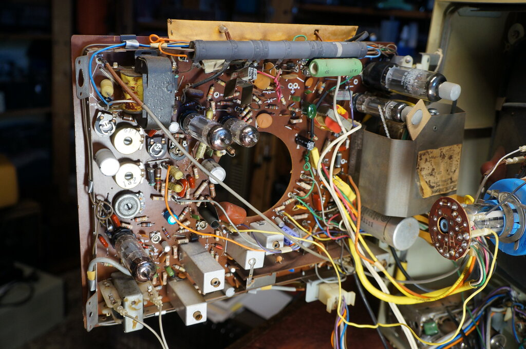
Tuner and controls ready for removal.
The Matsushita (National) tuners used in many of the Thorn R and S sets are very reliable and fault free. The contacts looked clean, but cleaned them anyway without improvement. It was while the tuner was out and the set was on, that I accidentally touched the 4GK5 RF amplifier valve. Whereupon the tuner functioned normally. Thinking about it, the symptoms were perhaps not surprising. The 4GK5 is a triode operating in a neutralised circuit. Should the neutralising not be perfect (e.g., from a dirty valve pin), then it's liable to oscillate. Hence the blank raster with herringbone observed previously. There was some green corrosion on the pins. It took quite a lot of pin cleaning to fix the problem, but that was it.
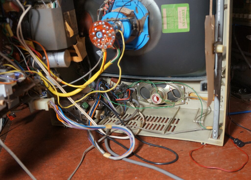
Tuner is to bottom left. Close examination shows re-terminated mains
cable with heatshrink tubing. Note the blanked off opening to the right
of the speaker.
This cabinet design was used for a previous Thorn set in the UK
which was dual standard. The opening accommodated the push button UHF tuner.
Careful observation of the white
twin flex cable at the bottom of the cabinet shows the tubular in
line connectors for reversing the mains polarity.
20 Ohm Anti-Surge Resistor.
Typical for a set like this, with the
first filter capacitor charged from rectified mains, is a surge resistor
in series with the rectifier diode. It limits the diode and capacitor charge
current, if the set is switched on when the mains voltage happens to be
at the peak of the cycle.
It's also kinder on the capacitor during
normal use, since the charging current during each half cycle is limited.
This resistor is part of the Osborne branded dropper which runs along the
top of the chassis.
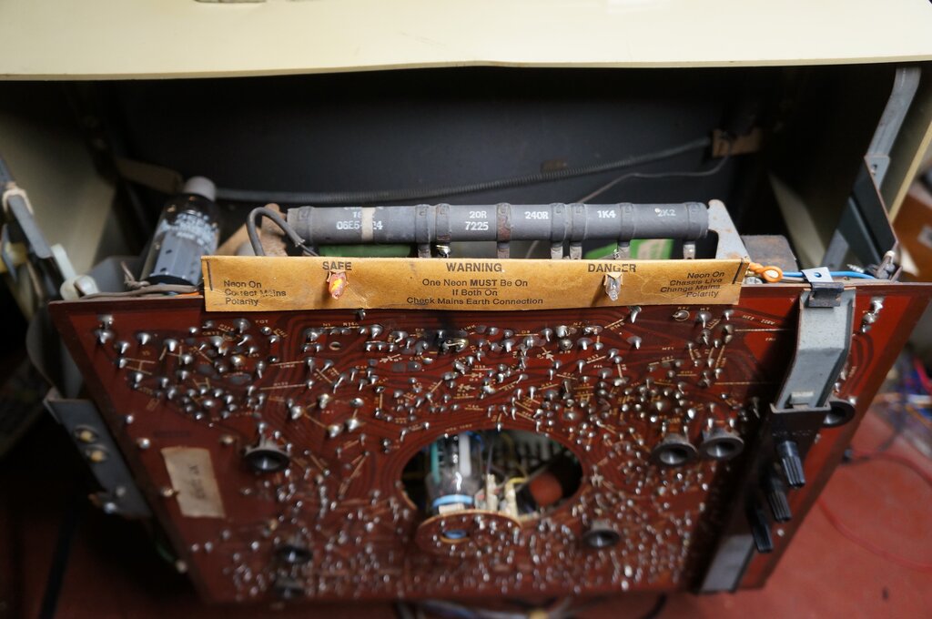
Polarity neons are visible here, as is the dropper resistor. Notice
the 20R section. This actually turned out to be OK. The restored connection
is visible on the left side of the 20R section. Note the 1972, 25th week,
date stamp.
At some time in the past, the 20R section
on the dropper had been cut out of circuit, and another resistor connected
in its place. This resistor should have a rating of 20W, but the replacement
looked more like 10W. No surprise it hadn't lasted therefore. However,
looking at the original 20R section, I couldn't see any corrosion or burned
part. And, I've not seen this section open in any of the other R2M's I've
worked on. Suitably suspicious, I applied the ohm meter probes, and I can't
say I was really surprised to find it intact.
This would be very convenient, because
tacking on another 20W resistor would be untidy. Unfortunately, our would
be technician had cut the connection where it entered the dropper, rather
than at the PCB end. Nevertheless, there was enough to restore the connection.
Because of the high temperature here, I wrapped tinned copper wire around
the severed connections before soldering. These connections are also of
mild steel, which meant they were rusty, aided by the heat. Careful cleaning
was needed therefore, prior to soldering.
With that done, the set worked perfectly
well with the original section.
So, why had someone felt the need to replace
this resistor section? Assuming this was done while the set was still under
Radio Rentals ownership, it could be assumed the technicians employed would
have been trained on these sets, and known the service procedure to identify
open dropper sections. One possible clue is from a repair on the PCB. There
has been a little burn up where the 20R section connects to the PCB track.
This is not surprising since the mild steel tag is difficult to solder,
and it gets hot. My guess is that the technician found no B+, and assumed
the 20R section was open, before noticing the open circuit was actually
on the PCB, and not the resistor itself.
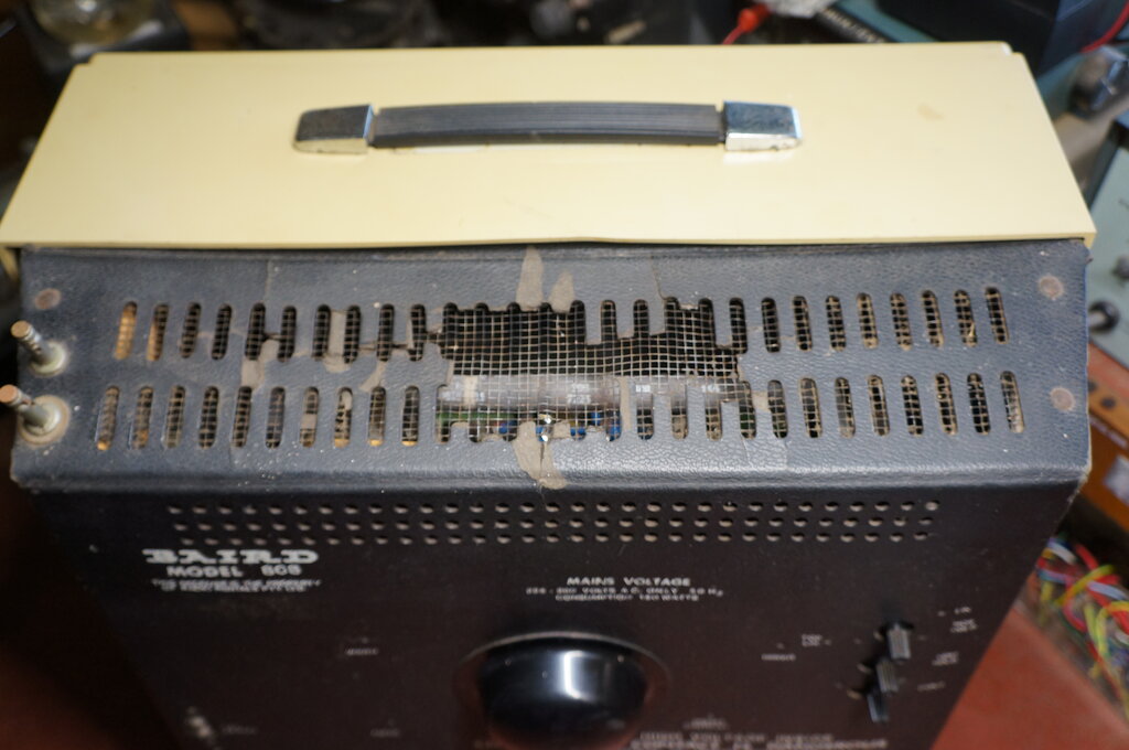
Unfortunately, the heat from the dropper causes the fibreboard to
deteriorate. This was addressed with the model 811.
Line Ripple.
While the set now produced a picture,
there was a very noticeable ripple in the line deflection. This was obviously
the difference between the mains frequency and that of the digital box
which generated the video signal. It was quite obvious and should not be
there. It's true that a half wave rectifier tends to show up filtering
imperfection, more so than full wave, but the R2M is normally very good
in this department. Two possibilities for its cause might be a heater to
cathode leakage in the 30FL2 line oscillator valve, or lack of capacitance
in one of the filter capacitors. Bridging a 33uF 350V capacitor across
each of the sections in the main can capacitor didn't achieve anything.
The line oscillator has a separate 10uF filter on the other side of its
B+ decoupling resistor (C63). Bridging this certainly did something - the
fault was gone.
The 10uF measured open on the ESR meter.
Replacing it fixed the fault with a completely steady picture.
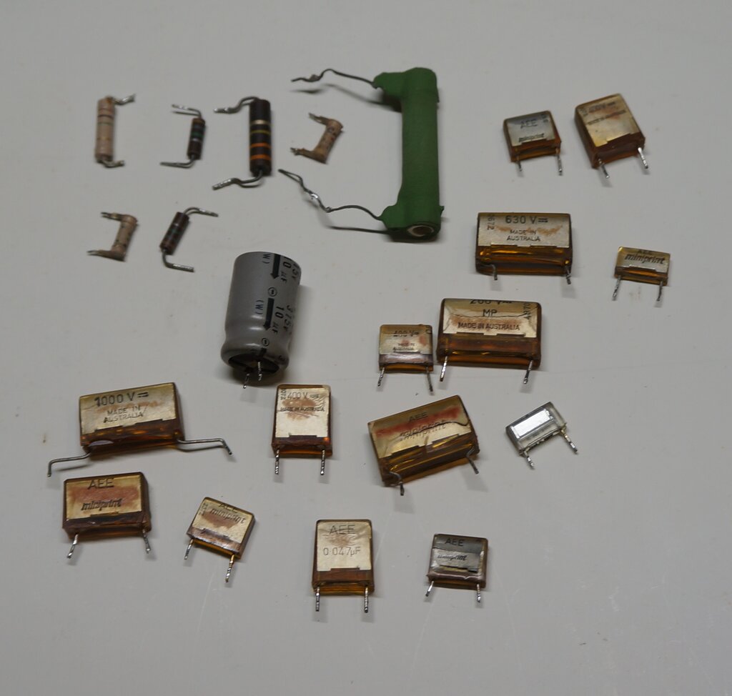
Parts replaced. The green power resistor was the 20R replacement
which had been used for the anti-surge resistor.
Resistors.
What of the resistors? Normally these
are fairly good, since for the most part they are not IRC.
There are some of the PCB mount type resistors of British origin which
I've found very troublesome in the Decca 33 colour sets. One which does
fail often in the Thorn R sets is the 1.5M in series with the focus control
(R131). Since this was inoperative, I replaced it and a few other likely
suspects. There were also some carbon IRC looking resistors which I suspected
and replaced also. I'd also suspected these because they were in the width
regulating circuit, and as it was, the width wasn't as much as it should
be, even with the correct boost voltage. These resistors were actually
OK, but it turned out to be one capacitor I hadn't replaced. This is described
further down.
Height.
One thing noticed was that a 1M resistor
had been soldered in parallel to R108 (1.2M) which is the frame oscillator
plate load. Servicemen do this kind of thing when the height control has
run out of adjustment. It was suggestive of R108 being high. This measured
1.58M.
While out of tolerance, it wasn't that
much so. Naturally I replaced it, since it was also one of those English
PCB mount resistors which I don't trust. After removing the foreign 1M
and replacing R108, it was found the height control needed to be a fair
way up, with not a lot more adjustment left. None of the other resistors
measured high. Measuring the waveform at pin 3 of the PCL85 (frame oscillator
plate) showed that, if anything, the amplitude was slightly more than the
80Vp-p which the circuit shows. Similarly, testing at the pentode grid
revealed a little more than the 75Vp-p specified. Another PCL85 did not
increase the height at all.
There are two discrepancies however. The
B+ for the frame output is specified at 225V, but I measured 204V. None
of the filter capacitors were faulty, so I can only put this down to mains
voltage. The more strange thing is the plate supply for the PCL85 triode.
According to the circuit it is 250V, stabilised by the VDR, Z1. I measured
about 320V. As there is still some adjustment in the height control I am
not worried about all this, but more curious how the triode plate could
produce enough peak to peak voltage with only the specified 250V.
CRT.
From the general condition of the set,
it appeared to have had a lot of use. For one thing, some of the channel
numbers are worn off the knob. The amount of plastic warpage at the back
of the cabinet top is another indication. The 'safe' polarity neon was
flickering which suggests many hours use. It was also slightly disconcerting
that when I did finally get screen illumination, that it wasn't as bright
as it should be. Normally, these 17" Ediswan AW44-120W/R CRT's produce
a very bright and sharp picture. I wasn't overly concerned, since I do
have a couple of spares, and there was also the possibility of reactivating
it. However, it's important not to jump to conclusions - something that
so many would be TV restorers do.
Bit by bit, as the capacitors and resistors
were replaced, it did come good enough without the need to reactivate the
CRT. The brightness is ample, and although there was some flaring on peak
whites, this disappeared after a while. Also, having laid dormant for many
years, just putting a tube back into use after this length of time can
often 'wake it up'. Gas inside the tube (the vacuum does not always remain
perfect) accumulates on the cathode, which impedes emission. Running the
cathode boils it off again. By the time I'd run the set for quite a few
hours after all the other work, it was in quite good condition. In a few
days, it was putting forth a really excellent picture; just as good as
I remembered with these sets.
On this subject, reactivating CRT's should
only be attempted if it is known the operating conditions are correct.
The stripping of the cathode to expose a new emissive surface is permanent.
Once that material is gone, it's gone forever. Similarly, picture tube
brighteners damage the CRT by over running the cathode. Sadly, these devices
are often used by the lazy or ignorant to mask other faults, ruining what
might have otherwise been a good CRT.

Typical off air picture. It's actually sharper in real life. When
taking photos of TV pictures, a long exposure is needed to avoid seeing
a blanked section.
S-Correction Capacitor.
And here, I must admit that I hadn't actually
replaced every one of the AEE Miniprint capacitors. C99,
the S-correction capacitor was still original. Since it passes the entire
current for the line coils in the deflection yoke, it handles a reasonable
current. So, it's best to use something decent to replace it. This S-correction
capacitor is also what I consider an uncommon value; 0.18uF, which is why
I hadn't got around to replacing it. I hadn't really given it a lot of
thought, since I'd assumed leakage shouldn't be problematic, as there was
not actually a lot of DC across it. Not long after replacing the resistors,
and thinking what to do next about getting the correct width, I noticed
a cooking smell, except no one nearby was cooking. Then a waft of smoke
appeared above the line output section, emanating from C99. Pretty obviously
it needed to be replaced.
To make up the value, I used a 0.1uF and
0.082uF Philips polycarbonate in parallel. That fixed the problem, and
the width was as it should be.
Next to the line output shield is an orange wire. Right next to
that can be seen the yellow replacement S-correction capacitors. You can
also see the green replacement 180 ohm heater dropper right under the open
circuit section. It's important when doing this to cut away some of the
original, as was done here, in case it should make connection again.
Preset Controls.
On the back are three lesser used controls;
Hor. Hold, Vert. Hold, and Contrast. Because of the way they protrude
from the back they are easily (and often) broken. This set was no exception,
and the Hor. Hold knob was broken.
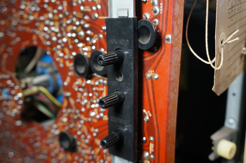
Protruding from the cabinet back, these knobs are in a vulnerable
position.
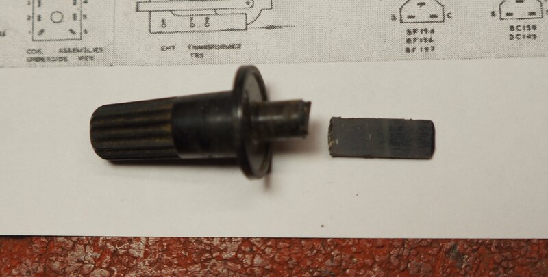
Knobs usually break like this.
It's possible to get away with not actually repairing the knobs since these controls seldom need adjusting. Alternatively, they can be swapped around. For example, the most used control would be the contrast, and if it's this which is broken, it could be swapped with the line hold knob. Since this is a restoration, I fixed the knob. This entails cutting a slot in the knob shaft with a Junior hacksaw, widening it with a jeweller's file, and reinserting the broken flat part. The material appears to be something like polyethylene, which is difficult to glue. I have used epoxy in the past, but it can separate, especially because the flat plastic part is flexible. Contact cement would probably work quite well, but I have not tried it. Neither have I tried super glue. In this instance, I've used a polycarbonate cement which can work well on 'difficult' plastics. Time will tell, but in reality this knob is so rarely, if ever adjusted. A 1mm hole drilled through the two pieces, with a piece of wire inserted to lock them together, would provide additional reinforcement.
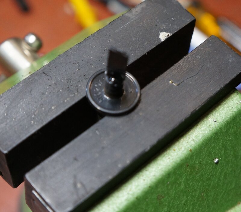
Repaired knob.
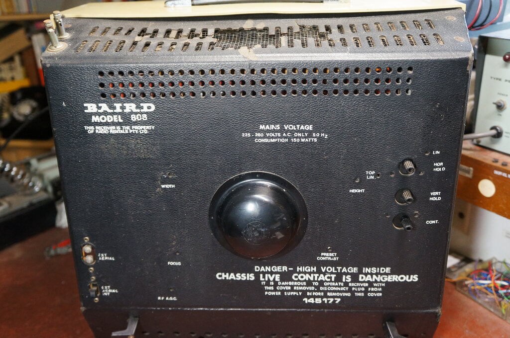
Back of set. Note how vulnerable the preset knobs are.
Video Fault.
A restoration isn't usually complete without
a few extra faults that show up later, and are usually intermittent. One
fault I had occasionally observered was a loss of video and sync. It looked
a lot like the AGC circuit was throttling back the gain, to the point where
the picture was so weak as to be unrecognisable, and also so weak that
sync was lost. As this set uses AC coupling throughout the video circuit,
the screen still remained at normal brightness. I recall my first 808 also
had this intermittent fault, which I never fixed.
The likely suspects in the AGC circuit
were electrolytic capacitors C53 and C54. Also R72, being a high value
English resistor was suspect. I replaced these parts; only the resistor
measured high at around 270k. The capacitors tested OK, but bearing in
mind it was an intermittent fault, that doesn't prove anything.
Unfortunately, before long the fault was
back. Remembering back to the Baird 812 and its faulty video detector diode,
I decided to check the actual video signal. And here, we got somewhere.
In normal and fault conditions, a normal video signal was present up to
the emitter of the video driver transistor T6. By now the fault was starting
to appear more frequently, and it didn't take long to narrow it down to
the contrast control itself. I had noticed the operation was somewhat abrupt,
even after squirting it with CRC. The contrast control is simply a rheostat
in series with the video signal, feeding the base of the video output transistor.
Like a lot of potentiometers wired as rheostats, the wiper is connected
to one end of the track. The idea is that even if there's a noisy wiper
connection, the maximum resistance can never be more than the track, rather
than being a total open circuit. So by that theory, the video signal should
never have got so weak as to lose sync. That is, unless the rivetted connection
between the track itself and the tag was the fault. In this instance, the
way the PCB tracks are laid out, there is some slight capacitive coupling
for the video signal, even when the pot was completely open, which explains
something still being visible.
The contrast control is 1.5k and a PCB
mount tab pot. The nearest I had was 1k, and a conventionally wired tab
pot. As the normal setting of this pot was towards minimum resistance,
I figured 1k would be enough. The pot mounted to the PCB without problems,
and I used short pieces of wire to connect it to the PCB. It was completely
successful, with plenty of adjustment, and the fault did not return.
Height Variation.
Another intermittent also showed up. There
was an ever so slight reduction in height. Most non-technical viewers would
not have noticed it, but I can't consider the job finished leaving it like
that. A likely area to start is the frame oscillator supply to the PCL85
triode. Measuring the voltage across the Z1 VDR showed this to be stable
at 314V despite the height variation. The fault had to be between here
and the PCL85 plate. R106 had already been replaced, so it wouldn't be
that. Measuring the voltage across C81 did show variation, which meant
this was faulty, or the preset height control in series with it. Most likely,
it was the capacitor, and being a 1uF high voltage electrolytic, this in
itself is cause for suspicion. Indeed it turned out to be so. Not only
that, upon replacing it, more adjustment was now available in the height
control, which would indicate this capacitor was not only intermittent,
but had been slightly leaky all along.
With these remaining faults fixed, the
set has been 100%.
Baird 811 is a later version of the 808. This set is not mine but
the photos were supplied by a reader.
The Baird 811 is the same as the 808 except for two minor cabinet styling differences. The "Baird" emblem on the front panel is part of the speaker grille, and the top of the cabinet back has a plastic grille to better withstand the heat. It appears that the 811 was sold rather than rented, since "This Receiver is the Property of Radio Rentals Pty. Ltd." is not printed on the back cover.
Other Sets.
Not all sets in this cabinet are branded
Baird and use the R2M chassis. The Thorn 7136 can have either an R1 or
R2 chassis.
Thorn 7136 fitted with an R1 chassis.
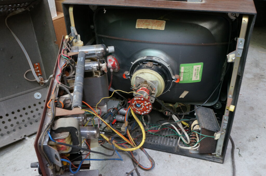
Note the power transformer. This set has a Philips yoke.
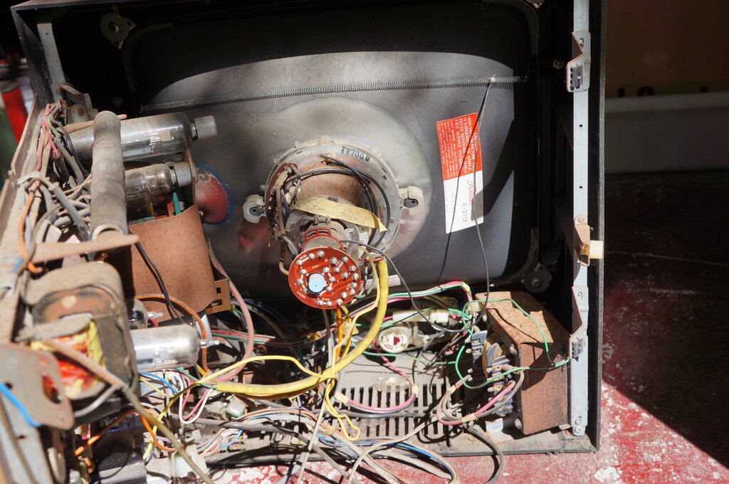
This is inside another Thorn 7136. It looks the same, except this
has the R2 chassis with series heater valves. Note that it still includes
the power transformer. This set has a Toshiba CRT, which indicates later
production.
Note the shield around the preset controls on the back cover. These
knobs are often broken on earlier sets.
This set has an unknown model number (presumably 7136). It has an
R1 chassis.
It is impossible to tell what chassis is inside one of these cabinets without looking inside. The R1 and R2 are just as heavy as each other, and the only difference is the valve types and that the heaters are in series. The R2M is however identifiable, because of the live chassis warning printed on the cabinet back. To date, all of the Thorn branded sets seen have been R1 or R2, and only the Baird have been R2M.
The use of the same dropper resistor in the transformer powered sets is interesting since two of the sections are not used. One wonders if when Thorn decided to go into production of the R series, that a live chassis version was already on the cards. No doubt, Radio Rentals in Australia would have known of the success of the 1500 in the UK with their parent company, and were keen to introduce it here. It's quite possible they encouraged Thorn to provide for the live chassis version, since production costs would be much less. The PCB's are same between all three versions of the R series, and because the heater wiring is not on the PCB itself, it's a simple matter to configure it for series or parallel working. Similarly, the PCB allows for the different rectifier configurations. The anti-surge resistor is not used with the transformer sets, since the secondary winding provides the necessary resistance.
Service Notes.
From Videotronics, April-May 1973, and June-July 1974.