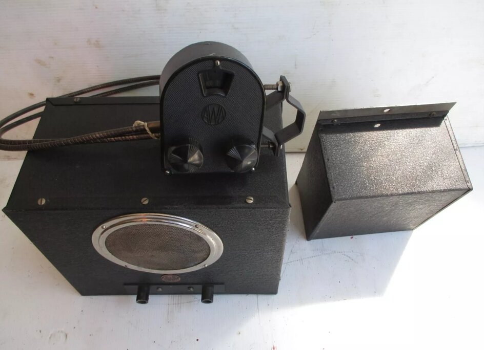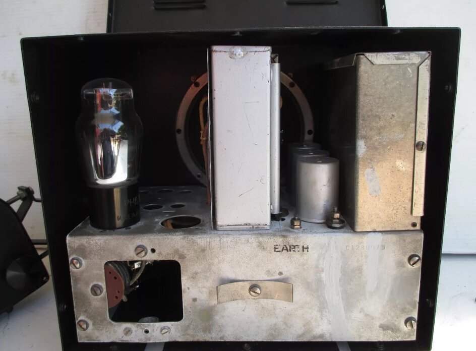
AWA 74 car radio (eBay image).
The following is adapted from an article published in the HRSA Radio Waves magazine, January 2020.

AWA 74 car radio (eBay image).
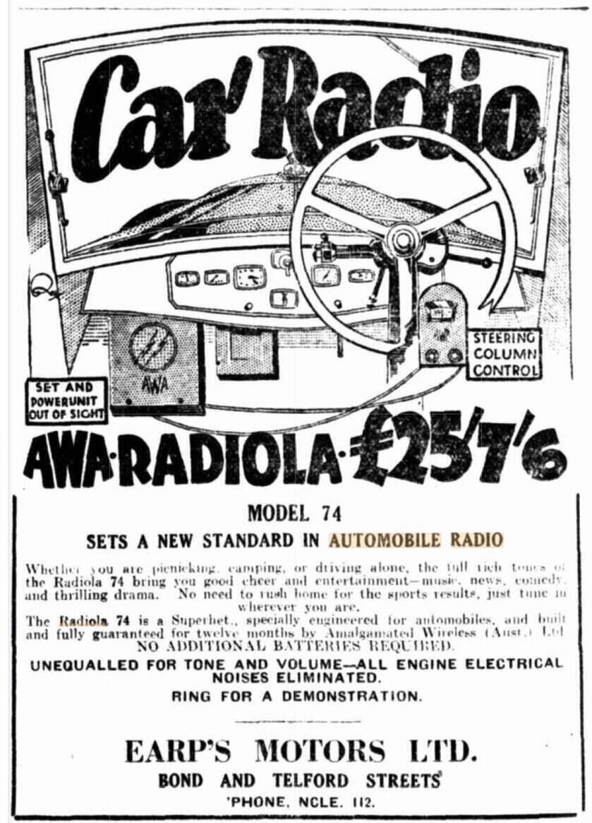
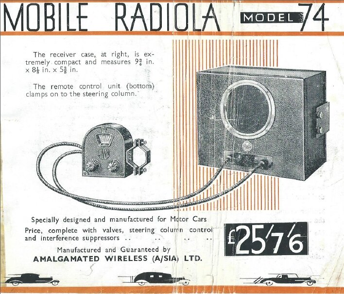
With an interest in car radios and vibrator technology, I was interested to learn that a fellow HRSA member had a Radiola 74; the first AWA set made for car use, dated from 1934. He described it as essentially a Radiolette R27 mantel set chassis, adapted for remote control via Bowden cables, and with an external vibrator power supply. The vibrator was unusual being inside two felt lined cans.

The R74 is a domestic mantel radio adapted for car use (eBay image).
When I saw photos of the vibrator, I immediately
recognised it as an RCA type 7604, produced for their M34 car radio in
1933. While it may be assumed that AWA always used Oak vibrators, this
was not always so. Prior to 1939, an imported Electronic Laboratories type
was being used, and prior to that, the RCA type which is the subject of
this article.
He asked if I thought the vibrator could
be restored. This was a challenge I eagerly accepted, with the chance to
examine one of the first vibrators and test its performance, comparing
it to the later types that most collectors would have seen.

Power supply is separate to the receiver.
To explain the significance of the RCA
vibrator, it is necessary to set the scene with the early technology. Various
rotating and vibrating devices were tried in the early 1930’s to obtain
the necessary B+ from the car’s 6 volt battery. The outcome was two competing
methods; the motor generator, and the vibrating interrupter with a transformer.
The motor generator worked well, but it could not compete with the lower
cost, and quieter, more efficient operation of the vibrator.

The later version of the 7604 was fitted with a lead seal.
The first commercially made vibrator power supply was marketed in 1932 by the P.R. Mallory Co. It was a half wave type with a Raytheon BR gas rectifier. In 1933-34, Mallory were producing a self rectifying vibrator, which was also half wave. These power supplies were a stand alone unit, intended to take the place of the three or four 90 volt B batteries, otherwise required for car radios up until this time. Galvin Manufacturing (Motorola) was the first to build the power supply into the set itself, and this they did using the Mallory vibrator.
As is well known, central to all vibrator designs is a reed with contacts mounted upon it. As the reed vibrates, the connection to oppositely mounted fixed contacts is alternately made and broken, thus converting the DC battery supply into pulsating DC or AC, which can be stepped up by a transformer. The reed is caused to vibrate by means of an electromagnet switched by contacts on the reed, in the same manner as a buzzer. A few designs used up until 1933 excited the reed by using the magnetic field produced by the transformer itself.
One of the breakthroughs with vibrator design was the method of reed excitation. With the first Mallory type, the driving coil was in series with the supply to the transformer. A disadvantage with this method is that reed vibration is dependent on the loading of the power supply. This is critical to proper performance. Also, should the vibrator fail to start, a very high current will be drawn because of the low driving coil resistance.

Early half wave vibrator circuit.
These problems were overcome with the introduction
of the shunt drive vibrator. The driving coil is of much higher resistance
and operated in shunt fashion, across the contacts which are now normally
open, or across the battery supply with its own contacts. The driving coil
current is no longer dependent on transformer loading. The high resistance
coil prevents any harm occurring if the vibrator does not start.
The other major development was the full-wave
vibrator. This was more efficient than the half wave design, since the
transformer was being fed with proper AC, eliminating the core saturation
problem inherent with pulsating DC, and a much higher output could be produced.
The shunt drive full wave design quickly became standard for all vibrators.

Shunt drive circuit. Driving coil has separate contacts with some
types.
The RCA 7604 vibrator is significant in that it is one of the very first shunt drive full wave designs. It was also of the first generation of synchronous (self-rectifying) types.
The RCA 7604 Vibrator.
The first noticeable aspect of design
was just how large this vibrator is. The outside can is 110mm high by 65mm
diameter. Contrast this to a “modern” type in a can 80mm by 35mm.

Patent drawing of the RCA 7604.
The vibrator mechanism is assembled on
a Bakelite frame which is secured to an alloy base by a rubber cushion.
A felt lined aluminium can covers the mechanism and screws to the base.
A second larger felt lined can then screws over this.
The vibrator base is bolted to the chassis
of the power supply, and connections are made via flexible wires. In some
early vibrators, the timing (buffer) condensers are mounted in the vibrator
itself, and the 7604 is of this type. Here, the condensers are encapsulated
in pitch in the alloy base.

Timing condensers extracted from the base.
There are five pairs of contacts. Two for the primary interrupter, two for the secondary rectifier, and one pair for the drive coil. Across the drive coil contacts is a 50 ohm resistor. Its purpose is to reduce sparking, by slowing down the rate at which the magnetic flux in the drive coil collapses, when the contacts open. Measured operating frequency is approximately 75c/s. Later types of radio vibrator standardised mostly on 100, 115, or 150 c/s.
The construction is quite interesting because it shows just how rapidly vibrator technology improved soon after. In fact, this vibrator is somewhat reminiscent of an ordinary relay in how the contacts and armature are constructed. The drive coil is large and makes the mechanism quite top heavy.
Rubber Cushion.
As received, the vibrator mechanism was
floating loose in its can with the rubber cushion (part 26 in the patent
drawing) having completely perished. The rubber insulation of the connecting
wires was also becoming brittle and breaking off. The first part of the
restoration would be to replace the cushion. The mechanism of a vibrator
must be allowed to float, otherwise the amplitude of the reed vibration
is damped and performance suffers. A very spongy rubber is usually used
between the mechanism and the base. What to replace this with and how to
attach it, was the immediate challenge.

Rubber cushion has completely perished.
Seeing as the pitch and timing condensers
would have to be removed from the base, I came up with the first idea.
By using silicone sealant, I could secure the mechanism to the base with
a degree of flexibility. The base would be filled with silicone, and by
screwing a disc to the Bakelite, spaced off it by a few millimetres, the
silicone, once dried, would secure the mechanism.
A metal disc was cut out and two 5BA holes
drilled and tapped into the Bakelite to secure it. Once assembled and placed
in the base, the base was injected with silicone.
This seemed very promising, but alas when it came to testing, the reed vibration was very weak when the base was held in the bench vice. Obviously, the silicone was not flexible enough and the mechanism was too heavily damped.
Thinking over this for several days didn’t come up with anything useful, except somehow I needed very flexible rubber, and had to secure it to the alloy base and the base of the mechanism. I then found some foam tubing of the kind used to insulate hot water pipes. The diameter would make a nice fit into the base and could be contact cemented in. To attach the Bakelite I could screw some kind of plug to the centre and then glue the whole thing to the inside of the foam tube.

Foam rubber tubing was contact cemented into the base.
This idea worked perfectly. Now the reed amplitude was unaffected by how the base was mounted.

Plastic cup and Bakelite were contact cemented into the foam rubber
tubing.

New foam rubber allows vibrator to float on its base while remaining
attached.
Contacts.
As is typical with first generation vibrators,
the mechanism was designed to be serviced with replacement parts made available,
and part numbers are given in the service manual. With the contacts being
covered in a very thick layer of tungsten oxide, it was easy to dismantle
and clean them with a points file. Unfortunately, one contact of each of
the pairs of interrupter and rectifier contacts was very badly worn, with
little tungsten left. RCA specify a gap of 0.015”, but there was at least
double this.
Why were the contacts so worn? Ultimately,
it comes down to operating conditions and the choice of materials used
in the construction. Any vibrator, modern or old, will have a short life
if the operating conditions are incorrect. This comes down to aspects such
as input voltage, output load, and how well the buffer circuit is working.
The mechanical design is also very important.
Without going into extensive detail, every
vibrator power supply requires a buffer, or timing circuit, to tune the
transformer to the vibrator. The transformer is tuned by a capacitor connected
across one of the windings, so that the current in the primary winding
is at a minimum just before the contacts actually close, and just before
they open again. In this way, electrical wear of the contacts is avoided.
It is the current flow while the contacts open and close, rather than only
when they are closed, that causes erosion.
When the 7604 was being developed, knowledge
of timing circuits operation was in its infancy. To a large extent, the
value of timing capacitance was selected by trial and error. Essentially,
the capacitance was chosen to reduce the sparking to a minimum.
However, the problem with this method
is that there is a wide range of capacitance that will minimise the sparking,
but only one value will actually tune the transformer correctly. Contact
material transfer may still take place, with subsequent pitting and sticking,
in addition to high peak voltages or excess peak current; if the capacitance
is not correct.
It must be remembered that cathode ray
tube technology was in its infancy in the early 1930’s, making it difficult
to actually observe the behaviour. It wasn’t until the mid-1930’s that
timing circuits were properly understood.
Therefore, a possibility for the high
rate of contact wear was a less than ideal choice of timing capacitance.
In the 7604, this is two 0.04uF series connected condensers across the
full secondary winding, with their midpoint earthed. As the vibrator to
hand was so worn, there was no way I could tell if in fact the original
timing capacitance was optimum. Aside from frequency, duty cycle also affects
the choice of capacitance, and this needs to be increased for a lesser
duty cycle.
The way the tungsten is cut for the contacts
also has a bearing on how well they wear. Apparently, a vertical grain
gives the longest life. How fast the contacts make and break, and with
what pressure, also has a bearing on wear. Mechanical tuning of the reed
and contacts was a later development in the technology, which again improves
life and performance.
All these aspects of design were rapidly
improved on, and by about 1936, vibrators were now a reliable component
with a good life span. The result was an exponential growth in the car
radio industry, as the buying public began to see that car sets were just
as good as the one at home.
At this point, the reader may now realise
that a vibrator is not just a simple buzzer, but a highly developed precision
component, with critical operating conditions. The buzzer concept is nevertheless
useful in explaining the basic principles.
Adjusting the Vibrator.
Looking at the waveform with the vibrator
fed into a resistive load, some contact bounce was evident, even after
cleaning the contacts. However, experience tells that when fed into a transformer
load, the amount present shouldn’t be problematic. The contact bounce could
be due to the wider contact gap, with the reduction in inertia by the time
contacts touch. The change in springiness of the reed, which in this case
is two phosphor bronze arms, could also be responsible. Later vibrators
all used Swedish spring steel for the reed. Also, the contacts mounted
at the top of the reed instead of the bottom, as per later designs, could
mean they have less mechanical leverage applied, and thus reduced contact
pressure.
Initial performance was poor with low output;
around 180V. Also, the reed vibration was erratic. The duty cycle was only
about 70%. A “modern” vibrator typically operates with an 80% duty cycle.
Today, one would use an oscilloscope to
adjust the contacts, but in 1933, a less scientific approach is described
in the RCA service manual. Contact gap is set with feeler gauges, and contact
tension is determined by hanging weights off them. This is all then fine-tuned
by adjusting for minimum sparking.
It can be imagined that with service technicians
of varying dexterity, vibrator adjustment was a very hit and miss affair,
with the reputation of vibrator reliability being dependent on how well
it was adjusted. It is for this reason that after 1934, vibrators were
sold as a sealed component, adjusted perfectly in the factory, and replaced
outright if failure occurred. A later version of the 7604 was provided
with a lead seal.
To restore a reasonable output from the 7604, the contact gap had to be taken up, and the only way to do this was to slightly file down the Bakelite stops which set the contact spacing. If taken to excess, the contact surfaces will no longer be parallel, so as a compromise I decreased the spacing to give a 75% duty cycle.
Timing Condenser.
Of course, with a reduced duty cycle,
the original value of timing capacitance was too small. The ideal value,
as determined by the primary waveform, was 0.18uF in place of the original
0.04uF’s. However, 0.18uF is not available with sufficient voltage rating
unless specially ordered. As long as the primary circuit ‘sees’ the correct
capacitance, it doesn’t matter how it is connected to the transformer.
Ideally, it would be connected across the primary, but the very high values
required make this impractical, particularly with 6 volt circuits. For
this reason, timing condensers are usually connected across the secondary,
because the effective capacitance is increased by the square of the turns
ratio. Connecting across the full secondary will allow an even smaller
value than when connected across one half of the winding. The catch is
that the capacitor is then exposed to increasingly higher voltage. Typically,
a timing condenser connected across the full secondary requires at least
a 1200V rating. When connected across half the secondary, 600V types can
usually be used. Unfortunately, this high voltage requirement was a problem
in the days of paper condensers, and short vibrator life was often the
result of a leaky timing capacitor.
Thankfully, with modern plastic film capacitors
this problem has been eliminated.
With the new operating conditions of the
vibrator, I found that 0.33uF across one half of the secondary provided
the correct timing, and was a common value.
The value of capacitor is a compromise,
and must be checked for suitability over the normal variation of input
voltage. For a 6V car electrical system, 5 to 7.5V should be allowed for.
Secondary Contacts.
The RCA 7604 is a synchronous vibrator.
That is, a second set of contacts operate in synchronism with the primary
contacts, to rectify the AC from the transformer secondary. This saves
the space taken by a valve rectifier (and its heater current).

Basic synchronous circuit. Separate drive coil contacts used in
this example.
Synchronous vibrators were therefore popular with domestic sets, where it was essential to minimise battery drain. For car sets, preference was given to non- synchronous types, since this type is not conscious of input polarity. In an era when there were just as many positive earth cars as negative earth, the transformer connections would otherwise have to be reversed, if the set was made for one polarity, but installed in a car of opposite polarity. A reversible vibrator base was later developed, which allowed the vibrator to be inserted in one of two ways, automatically making the correct connections. Despite this, the non-synchronous type remained popular with car sets, where the extra drain of the valve rectifier was unimportant.
With the AWA 74, both polarities are allowed for by swapping over the wires connected to the vibrator secondary contacts on the terminal panel.
The timing of the secondary contacts relative to those of the primary is important. They should open and close just before and after the primary contacts. This is done simply with a slight increase in contact spacing. It is interesting to note that the RCA service information specifies the same contact gap for primary and secondary contacts, which suggests this aspect of vibrator operation was not understood at the time. The reason for this contact timing is so that the B+ filter condensers are fed with current only when the polarity is not changing.
Some difficulty was had adjusting the secondary contacts, and it was necessary to do some more Bakelite filing to decrease the contact gap. Once this was done, the vibrator was now performing acceptably with a steady output.
If originality was not important, it would have been possible to use a valve or silicon rectifier. The vibrator could be wired as a non-synchronous type with the now unused secondary contacts connected in parallel to the primary contacts. Indeed, the vibrator worked very well when tested this way.
The 74 Power Supply.
The AWA 74 is known as a “two unit” radio.
That is, the power supply is in a separate box to the receiver. This arrangement
existed with some car radios until the 1950’s and was done to maximise
installation convenience, particularly for small cars.
Although the vibrator was imported from
the U.S., the other components are all of AWA manufacture. Aside from the
vibrator, there is nothing in common with the RCA M34 car set.
The components are assembled on a simple
steel chassis with a terminal panel providing connections to the receiver
cable, and to mount the various filtering components.

Circuit of the 74, with modifications for Oak vibrator.
From notes on the 74 circuit diagram, it
can be seen that for later replacements, an Oak V5124 vibrator was used;
this becoming available in Australia around 1938-39. Schematically, this
is the same as the RCA vibrator, except the V5124 has a UX-6 base, and
the pin numbers have been written on the circuit. Also, the 50 ohm resistor
is not present with Oak vibrators; a short circuited secondary winding
of resistance wire on the drive coil taking its place. The timing condensers
have also been shown as 0.02uF instead of 0.04uF. This is to be expected
as the RCA vibrator operates at around 75c/s instead of 100c/s for the
Oak.
As an experiment, I did wire in an Oak
vibrator, but found the timing condensers should be closer to 0.05uF for
the correct waveform. Incidentally, the design could be improved by including
resistors in series with the timing condensers, to limit the discharge
current when the rectifier contacts close.
It was noticed that the other capacitor
values were not as portrayed on the circuit diagram. Instead of the 0.5uF
B+ filter and 0.25uF filter for the 6V input, a pair of small mica condensers
existed. They are unmarked except with a blue and yellow dot, and measured
about 670pF. This seems a very low value to be used in these locations,
and it’s possible the values shown on the circuit were a later modification
to improve RF filtering.
The only paper condenser in the power
supply unit (0.25uF), at the vibrator input, was left in situ, since being
connected across the 6V supply, any leakage is harmless.

Corrected circuit with original 670pF condensers and new 0.33uF
timing condenser.

Load testing with a 15W light bulb.
The power supply was given a 30 hour soak test using a 240V 15W light bulb. This is an ideal load since the current draw is about 60mA – typical of most sets with a 250V B+. Output voltage remained stable around 235V.
Conclusion.
Having worked on the previously mentioned
Mallory half wave vibrator, it was fascinating to see the next stage of
the technology.
When one looks at the development in vibrators
by the 1950’s, these early types seem quite primitive. Not only had the
size been considerably reduced, but the power rating substantially increased
– this along with a tremendous increase in operating life; in many cases
outliving the sets they were installed in. A better understanding of how
the circuits actually worked, along with much improved mechanical construction,
and materials appropriate to their function, all contributed to this. It
is interesting to speculate how the car radio industry may have turned
out, if it was not for the successful development of the vibrator power
supply.


