This inverter project goes back to 2006,
as an attempt to build a solid state inverter with around 80W output.
In April 1997, Electronics Australia described
a 15W 12V to 240V inverter intended to operate a CD player in a car. It
was essentially a much simplified version of the EA February 1979 300W
inverter, in that the output regulation is achieved by varying the pulse
width of the output waveform. By 1997, MOSFET's were the preferred output
devices, and the new design used these instead of bipolar transistors.
My intention was to use the circuit with a larger transformer, and uprated
MOSFET's. Additionally, I had already developed an auto-start circuit which
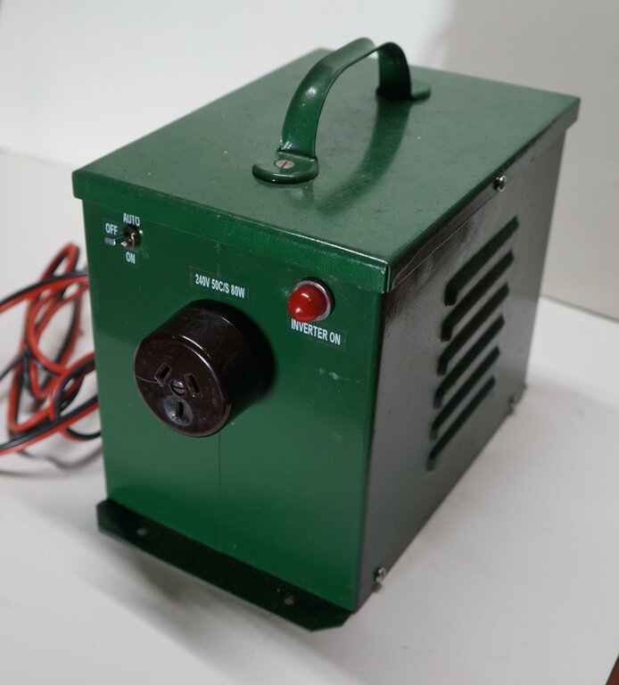
would be included. The inverter was housed in a case which once held an
isolating transformer.
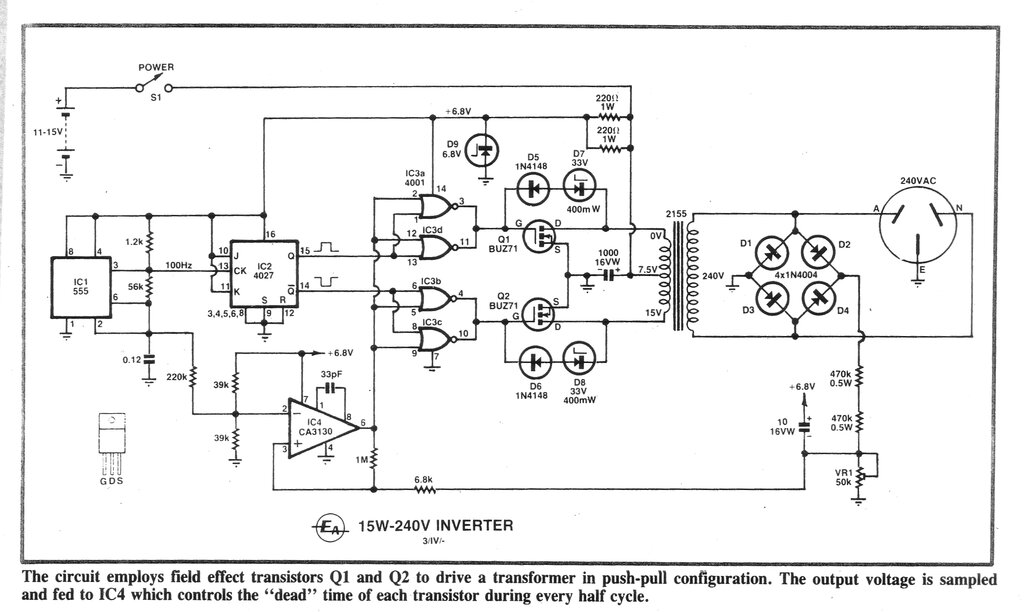
The EA April 1997 circuit which I initially based the inverter on.
In view of the higher power, I used paralleled
IRF640's for the switching MOSFET's. Due to the auto start circuit
requiring one side of the transformer secondary being close to earth, the
voltage regulation circuit had to operate in half wave. This meant deleting
D1, D3, and D4. Because of the resulting higher ripple, the 10uF was changed
to 47uF. I also changed D9 to 8.2V, and found it necessary to add 47uF
across the now 8.2V supply, for stability.
The transformer was one which I had rewound
the low voltage winding of, to 9-0-9V. It had previously been used with
this
inverter, albeit unsuccessfully with too high of a magnetising current.
I thought it might be less problematic with a solid state inverter.
To cut a long story short, the inverter
was built up with this transformer and appeared to work. However, the idle
current was higher than I would like, drawing about 1A, and the inverter
radiated so much RFI that powering a radio was difficult. Bypass capacitors
in numerous places only partially helped. The inverter was given up on,
and placed in my inverter cupboard for the next 18 years.
In 2024 thoughts had turned to resurrecting it, partly because of the increasing power prices, and wanting to get more onto my 12V solar supply - in this instance, some modems which draw a constant 30W. In the intervening time, I had learned more about transformer saturation and wondered if this was the problem. Perhaps changing to another transformer would fix it. As it happened, I had an 80VA toroid spare, which would no doubt improve efficiency.
Transformers and Inverters.
The use of a readily available mains transformer
used in reverse is a convenient choice for an inverter, and many such circuits
have been published. There are several things to take into account before
such use of a transformer will be successful.
Foremost is of course the turns ratio.
At first glance one might simply assume the use of a 12-0-12V to 240V transformer.
To do so will invariably result in a low output voltage; around 190V. The
first thing to consider is that what is advertised as a 240V to 12V transformer
will not have the expected 20:1 turns ratio. The advertised 12V will be
for full load, and the turns ratio is actually slightly lower to compensate
for the internal resistance of the transformer. This means the off load
output will be higher; 15V would be typical for some transformers. The
important thing to know is that the turns ratio is instead related to the
off load voltage. In the case of a "12V" transformer which outputs 15V
on no load, the turns ratio is actually 16:1.
Now, what happens when this "12V" transformer
is used in reverse for an inverter? The output is 12 x 16 = 192V. And that's
on no load! On load, again because of the transformer losses, it may drop
down to 180V. The output voltage is lower again if the duty cycle is less
than 100% (e.g. 80% with a vibrator), and is also further reduced due to
saturation voltage of the switching devices. Bipolar transistors have higher
losses than MOSFET's.
To compensate for all of this, the turns
ratio has to be higher, and a typical turns ratio for a 12V inverter transformer
might be around 24:1 to 26:1. In other words, a suitable mains transformer
to use in reverse would have 9 or 10V secondaries.
Next thing to consider is the turns per
volt ratio. Because we're putting 12V into a 9 or 10V winding, there's
a possibility the winding will saturate. That is, there is not enough turns
per volt. This means in simple terms, current is still flowing beyond the
time when no further increase in magnetic flux is possible. The output
voltage stops rising, the input current increases, and the the transformer
gets hot.
The problem here is what to choose in
terms of readily available mains transformers. Turns would have to be added
to the 240V winding so that a 12V low voltage winding could be used. This
is seldom practical, but there is a trick which can work fairly well if
isolation between primary and secondary is not required. Remember that
there will be something like 24V across the low voltage winding, so if
this is connected in series with the 240V winding so the voltages add,
a useful increase can be obtained; perhaps getting towards 220V.
An example of this method was used with
a 12W inverter built
to power a 240V LED bulb.
Another consideration is the waveform.
Mains transformers are intended for a sine wave. With a square wave of
100% duty cycle, the peak voltage is reached immediately, and remains there
until the polarity reverses. It may well be that the flux has built up
to maximum amount before the primary voltage drops and reverses polarity,
and the transformer saturates.
Also is the question of magnetising current,
which can be quite high with some large transformers. This current is multiplied
by the turns ratio, so when used in reverse, it can be quite significant.
A few watts is trivial when the transformer is powered from 240V, but this
can easily translate to well over half an amp when current is fed into
the low voltage winding. Toroidal transformers are far more efficient than
the usual E-I laminated kind, and as such have a much lower magnetising
current. This makes them quite attractive for inverter use, and several
designs have been described elsewhere on this site, both for AC inverters,
and DC-DC converters.
Generally, the best solution is to simply
try a transformer to see what the magnetising current is, and to see if
it saturates. This will be obvious by a high current draw under no load.
When viewed on a CRO, some distortion will be visible if the transformer
saturates.
SG3524.
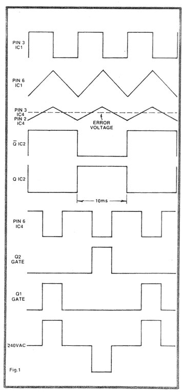
One of the things that concerned me with
the EA circuit was that the output pulse was not centred in the middle
of the waveform. I tried experimenting with the circuit with minimal improvement.
I suspect the problem was largely that the 'triangle' waveform at pin 2
of IC 4 was not exactly triangle, since the capacitor at pin 2 of IC 1
is not charged and discharged by a constant current. At this point I gave
up with the EA circuit and thought about the SG3524 IC. I built up a circuit
on a breadboard, along the lines of this
inverter. It worked considerably better than the EA circuit, with a
much better waveform. Unfortunately, as soon as the inverter was operated
with no load it became rather unhappy. The pulse width had to be reduced
completely to restore operation. The toroidal transformer was becoming
very difficult!
As a quick experiment I tried driving the MOSFET's with a sine wave, but the problem was they are not designed for linear operation, and it seemed the ones I had were not matched, since the resulting (and rather distorted) waveform was not symmetrical over the positive and negative half cycles.
Testing Transformers.
Clearly, the 80VA toroid had a saturation
problem, and I briefly considered trying other transformers. I first tried
a Ferguson PL18/60VA which is 240 to 9-0-9V at 60VA. This had the same
problems as the 80VA toroid. So what about a 12-0-12V transformer? How
low would the output actually be? A Ferguson PL24/60VA was then tested
with a 12.6V supply. This worked well as far as lack of saturation was
concerned, but as expected, output voltage was low.
| Load | Output voltage |
| No load | 237 |
| 15W | 224 |
| 40W | 209 |
| 60W | 200 |
No load current from the 12.6V supply was
400mA. This was tolerable, but these transformers are not the most efficient
anyway.
Next, a U.S. made Stancor transformer
was tested. This was rated at 12-0-12V at 2A. This was inferior to the
Ferguson, with only 209V across a 40W load - and that was with the primary
and secondary in series to add the voltages.
So, the Ferguson looked like a contender
if the 80VA toroid couldn't be used.
But first, let's see exactly what the limitation
with the 80VA toroid is. A circuit using a 4047 was built up to provide
a square wave with 100% duty cycle. This drove the MOSFET's in the usual
way. The circuit was based on this
inverter. The supply voltage was varied to find the optimum operating
point, and where the transformer saturated. This was determined by waveform
distortion coincident with a sharp rise in supply current.
| Supply Voltage | Load | Output Voltage |
| 9.6 | No load | 236 |
| 9.8 | 15W | 235 |
| 10 | 40W | 228 |
| 10.4 | 60W | 230 |
| 11.5 | 75W | 225 |
So, we could use this transformer
successfully, if the supply voltage was reduced. However, the method of
reducing the input voltage was important. At this point, it needs to be
mentioned there was a 10,000uF capacitor across the supply to the transformer.
Fed from a variable power supply, all was well, and this is how the figures
were obtained for the above table.
To make a practical inverter would require
the 12V supply be dropped by means of a power transistor, which could also
perform voltage regulation. To get an idea of the resistance required (and
heat produced) to operate the transformer from 12V, I then tried a laboratory
rheostat. Alas, we were back to the violent and unstable transformer behaviour.
What was happening is that with no load, the supply voltage of course rises,
and the transformer then sees 12V again. The bench power supply of course
maintains the same voltage on and off load, so the transformer operation
was always stable. The simple fix was to have the 10,000uF across the supply
before the resistor, so the transformer did not see the low impedance of
the capacitor. Now at last, everything was docile, and a way out of the
problem was now possible.
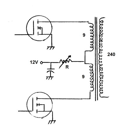
Resistor in series with primary supply prevents saturation and allows
control of output.
Series MOSFET.
For the series voltage dropping device,
another MOSFET was chosen. The disadvantage with bipolar transistors is
the high base current required, and the higher saturation voltage. First
thoughts were to put the MOSFET in series with the 12V supply to the transformer.
But then the gate voltage has to be higher than the supply. With a gate
turn on voltage of say 5V, the gate will need to be about 5V more than
the supply voltage, since the source will be around the supply voltage.
This would require additional circuitry to obtain the auxiliary higher
voltage of about 20V. The other alternative is a P-Ch MOSFET, but these
are less common, and not in my stock of parts.
The problem is easily solved by connecting
the MOSFET in the negative supply; i.e., in series with the drains of the
switching MOSFET's. The idea worked perfectly.
All we had to do was adjust the gate voltage
of the modulating MOSFET to control the output of the inverter. Provided
the voltage never allowed the transformer to receive enough supply voltage
to saturate, all our problems would be solved.
Sine Wave.
But, why stop there? What if we fed a
sine wave into the modulating MOSFET? We could modulate the supply to the
inverter thus, and create a true sine wave output. Where to get a sine
wave? As it turned out, this was quite easy by integrating the oscillator
output of the 4047.
With a suitable amplitude of sine wave
superimposed on the gate voltage, it worked surprisingly well. However,
the voltage range over which the output could produce a sine wave was limited
to about 40W. Above this, the transformer had to be driven harder, and
while the waveform was a lot less sinusoidal, it was far better than a
square wave. In fact, it was quite interesting to see just how docile everything
became when the transformer was fed a sine wave. Even a fluorescent lamp
operated well without complaint, and the output was free from any RFI.
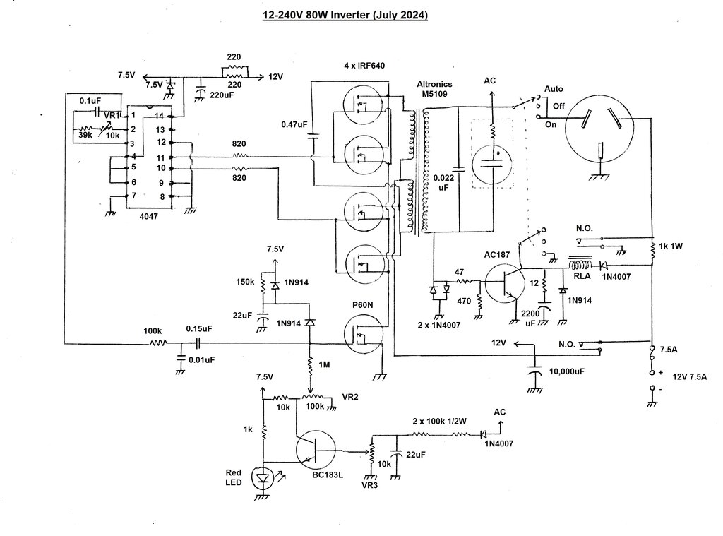
Circuit of the new inverter.
Oscillator.
The 50 cycle square wave is produced by
a free running oscillator based around a 4047 monostable/astable multivibrator.
A square wave with anti-phase outputs is available at pins 10 and 11. The
output has an even duty cycle which eliminates any DC in the transformer
- especially important with a toroid. The MOSFET gates are driven from
these outputs via 820R gate resistors which provide stability. The resistors
effectively form a low pass filter with the gate capacitance of the MOSFET's.
Their value is not critical, but if too high, the switching speed will
be slowed down causing the MOSFET's to run hot. Too low, and stability
might suffer.
VR1 sets the oscillation frequency. Supply
is 7.5V stabilised by a zener diode fed from the switched 12V supply. The
7.5V supply is also used for the regulation and soft start circuits.
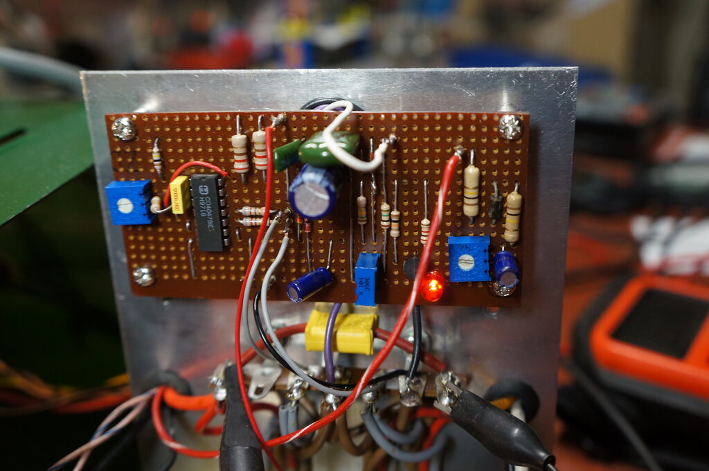
Constructed on Veroboard, this circuit contains the oscillator,
driver, and regulator circuits. Note the voltage reference LED.
Switching and Step Up.
Four IRF640 MOSFET's switch the transformer
primary. These are connected in two parallel pairs for each output phase.
More powerful MOSFET's have become available since 2006, and it would be
quite in order to use a single MOSFET for each phase. Since MOSFET's have
a low 'on' resistance, and they are being operated as switches, they run
cool and only require a simple heatsink. In this inverter, the aluminium
chassis was quite adequate.
As described previously, the transformer
is an Altronics M5109 toroid rated at 80VA. It has a 240V winding and two
9V windings. Note that there is a difference between Volt Amperes and Watts.
The 80VA rating means the transformer can power an 80W load, as long as
the load is resistive (e.g. incandescent lamp or heating element). However,
if the load should have a low power factor, the 80VA rating still stands,
but the wattage available is less. For example, the inverter can only provide
40W if the load has a power factor of 0.5.
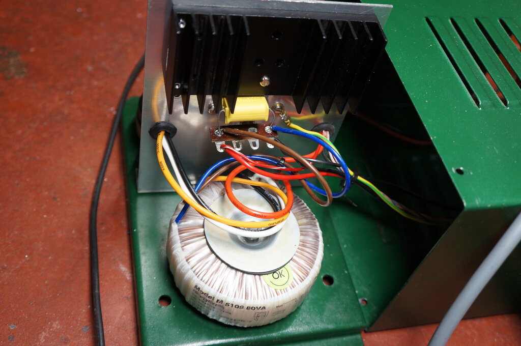
Toroidal transformer. It's a lot lighter and more compact than the
equivalent E-I laminated type. The finned heatsink is for the modulator
MOSFET.
The 0.47uF and 0.022uF capacitors across the transformer windings are a legacy of the original circuit. They do clean up the waveform and reduce RFI, so were left in situ. The 0.022uF is rated at 1600V DC, but a 250VAC type could also be used. Bear in mind, most such capacitors are of the self healing type, and their capacitance drops over time as the aluminium foil gradually burns away. A neon indicator is also connected directly across the secondary to show when the inverter is actually running. This is important due to the auto-start circuit, and that the inverter runs virtually silently.
Output Control and Regulation.
The drain circuit of the four IRF640's
is completed to earth by another MOSFET; a type P60N, which is rated at
60V, 60A, and can dissipate 150W. As the gate voltage is increased, the
P60N presents a lower resistance, and the inverter outputs a higher voltage.
The gate voltage comes from the 7.5V supply via the wiper of VR2 and the
1M resistor. And here we see the advantage of using a MOSFET. The gate
can be fed by a 1M resistor in view of the gate being effectively an open
circuit in terms of DC. It draws no current. If a bipolar transistor had
been used, the base current would be a couple of hundred milliamps, and
this resistor would be probably less than 100 ohms and dissipate a couple
of watts.
VR2 is adjusted so the inverter outputs
the highest voltage before the transformer saturates.
The regulation circuit operates in conjunction
with VR2. The 240V AC from the transformer secondary is sampled via a half
wave rectifier and a 200k series resistor. It is filtered by 22uF and applied
to VR3. The 200k resistor consists of two series 100k 1/2W resistors to
obtain sufficient voltage rating. It can be seen that as the 240V output
rises, so does the voltage across VR3. The wiper of VR3 feeds an error
amplifier of conventional design, using a BC183L transistor. The transistor
type is non critical, and a BC549 was actually used in the prototype test
circuit. The emitter is held at a constant 2V by the LED, which functions
as the voltage reference. If the base voltage starts to exceed 2V plus
the 600mV base to emitter voltage, the transistor conducts, bringing down
the collector voltage. The collector voltage supplies VR2. It can be seen
therefore, that if the AC output rises, the BC183L conducts which reduces
the P60N gate voltage, and the transformer is fed less voltage.
At this point, the inverter is practical
and fully functional. However, since the P60N is operating as a variable
resistor, it runs hot and needs good heatsinking. For example, if the inverter
is supplying 60W, the transformer should be supplied with 10.4V. Input
current under these conditions is 6A. If the supply is 12V, then the voltage
drop will be 1.6V. This translates into 9.6W of heat and wasted battery
power. If the battery is being charged and is up around 13-14V, the situation
is worsened, with 21.6W having to be dissipated with a 14V supply. When
the supplied load is 60W, having another 21.6W going up in heat doesn't
look very good at all from efficiency point of view (It's about 73%).
One may wonder about deleting the P60N
and simply controlling the gate voltage of the IRF640's to perform the
same function. Indeed, this was tried, but it was immediately obvious that
linear operation was not going to be successful. There was a difference
between the positive and negative half cycles, as if the MOSFET's were
not matched. Since they are designed as switches, this should not be surprising.
Furthermore, it's quite possible that the mismatching extends to the individual
MOSFET's in the parallel pairs, with the possibility one MOSFET might be
conducting more than the other, resulting in excessive dissipation. When
the MOSFET's are used as switches, they are fully saturated and matching
is not important.
The single modulator MOSFET approach means
that all the IRF640's work equally as switches, but the modulator
has exactly the same effect on all the IRF640's.
Waveshaping.
Since a MOSFET is being used as our variable
resistor to adjust transformer output, a logical extension of this is to
modulate it with a sine wave, which in turn should provide a sine wave
output instead of a square wave, thus more accurately replicating a mains
supply.
Experiments were done with some success.
First thing is what to modulate the MOSFET with. The waveform needs to
be a positive going half sine wave at 100 cycles. This is because each
phase (and pair of MOSFET's) conducts for 10ms. Remember, the 4047 is actually
oscillating at 100c/s since the creation of the two anti-phase outputs
effectively divides this by two. So, a 100c/s source is already conveniently
available. A simple RC circuit integrates the square wave into something
approaching a triangular shape. The circuit below was initially used for
waveshaping:
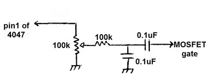
At the junction of the 100k and 0.1uF exists
a form of triangle wave. When fed into the modulator MOSFET gate, it just
so happens that because of the linearity of the MOSFET, that a reasonable
sine wave output is produced. The amplitude of the triangle wave is important,
so the 100k preset allows adjustment. Additionally, the gate DC voltage
is important, and is adjusted by VR2 as previously described. VR2 and the
100k preset are fairly interactive so need to be adjusted together, one
after the other.
I found that with a 15W load the sine
wave was quite good, and still acceptable at 40W, though the tops were
noticeably flattened. Even at 75W, the sides of the waveform still had
some slope. The heatsink could run somewhat cooler than if the inverter
was run with a 100% duty cycle square wave. Since it's a sine wave, the
transformer voltage can be run closer to the supply for a portion of the
waveform. Bear in mind that for a 12V supply, the sinusoidal peak is 9V,
and the transformer will not saturate.
The circuit shown above can be used for
anyone wishing to make this inverter in its sine wave form. Adjust for
best sine wave with a 40W load, assuming the same transformer. With the
particular components I used, it was actually possible to dispense with
the 100k preset and simply connect the 100k resistor straight to pin 1
of the 4047. This makes setting up easier, although the sine wave was not
quite
as good.
Variable Duty Cycle Square Wave.
The final version of the inverter, as
constructed, came about as a mistake while experimenting with the prototype.
Somewhere along the way, I had substituted a 0.01uF for the 0.1uF in the
waveshaping circuit. I didn't immediately notice at first, since the light
bulb load lit up normally as usual. However, I couldn't quite get the proper
sine wave - but then realised the inverter was operating even more efficiently.
What was happening is that modulator gate voltage was now of a much higher
amplitude triangle wave, and we now had a pulse width modulating circuit.
It seems the linearity of the P60N is such that with a higher amplitude
triangle wave was driving it into saturation much earlier. Depending how
far up or down the triangle the P60N switched determines the pulse width.
Gate voltage of the P60N. Depending how far up or down the waveform
the MOSFET switches determines the pulse width of the square wave output.
The heatsinking requirements are reduced. Even so, a proper finned heatsink is still necessary.
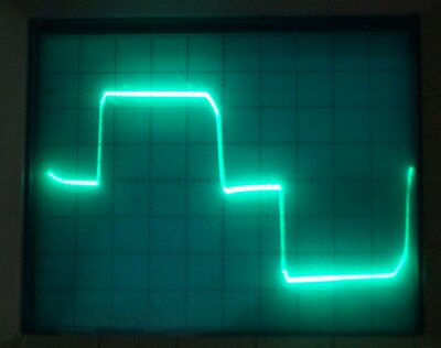
Source voltage of the IRF640's (Drain voltage of the P60N). The
solid line at the bottom is earth.
It should be noted that creating a sine wave output by the method described is not completely efficient, since the switching device(s) operate in the linear region. Inverter efficiency improves as the sides of the waveform straighten up.
Auto Start.
Quite some years ago I designed an auto-start
circuit for inverters. This saves running the inverter when the appliance
it is powering is switched off, and is particularly useful when the inverter
is remote from the appliance. This situation arises when the battery has
to be remotely located. Obviously, it is better to have the inverter at
the battery to avoid voltage drop, and to power the appliance through a
longer cable, where 240V overcomes any losses. It is often more convenient
to use the appliance power switch anyway.
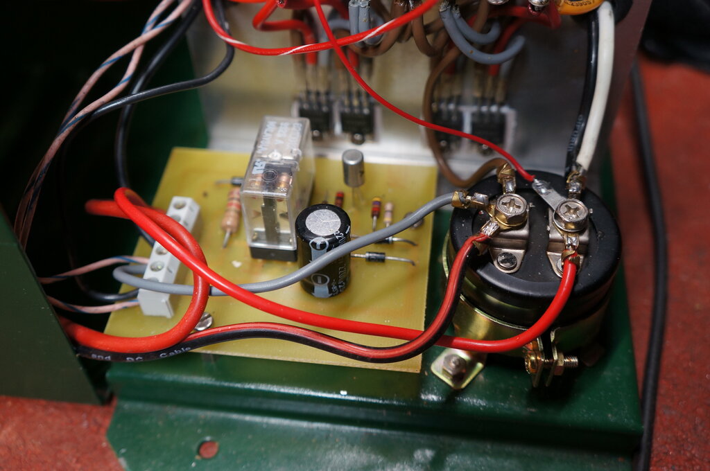
Auto start circuit on PCB. 10,000uF capacitor is adjacent.
Electronics Australia had used an auto-start circuit for some of their inverters. While it works, it loses about 2.4V of the inverter's output voltage. In the overall output it is only 1%, but I decided to improve on that, and also simplify the circuit. The EA circuit is shown for this 300W inverter.
Turning now to my auto-start circuit, one side of the transformer secondary is connected to the live pin of the output socket via a switch. The other side is connected to earth via to back to back diodes. The neutral pin of the socket is connected to earth via a set of normally open relay contacts. The inverter receives its 12V supply through another set of normally open relay contacts. Thus, when the relay is actuated, the inverter switches on, and the neutral circuit is completed.
Imagine the inverter at rest, but with
12V connected, and the switch in the auto position. An appliance is plugged
in and not switched on. Nothing will happen since the relay is not actuated.
When the appliance is turned on, things begin to happen. 12V flows via
the 1k 1W resistor, through the appliance, through the switch, through
the transformer secondary, and to earth via the right hand side diode of
the back to back pair. 600mV now appears across the diode, and biasses
the AC187 transistor into conduction via the 47R base resistor. The collector
current actuates the relay and the inverter starts.
Now there is AC across the back to back
diode pair. The opposing diode conducts on the negative cycles, so only
600mV is lost with this circuit. During the negative part of the cycle,
the transistor is not biassed, and the relay would normally drop out. That
is, except for the 2200uF which holds the relay in during the negative
half cycles. The 12R resistor limits the collector current when the transistor
first switches on. Since the 2200uF is fully charged when the inverter
is off, as soon as a load was connected, it would suddenly discharge through
the AC187. This current could be high enough to damage the transistor,
but with 12R in series, it can never exceed 1A.
When the appliance is switched off, the 600mV is no longer present across the back to back diodes, the transistor ceases conducting, and the relay deactivates, switching off the inverter. The 1N914 across the collector and emitter of the AC187 prevents any back emf from the relay coil damaging the transistor. In reality it probably isn't needed since the 12R and 2200uf would provide sufficient damping. In series with the relay coil is a 1N4007 diode. This provides reverse polarity protection for the inverter, since the relay cannot power up if the input polarity is reversed. No blown fuses if the polarity is reversed with this circuit!
The AC187 is a germanium type, chosen because the base turn on voltage is about 250mV. If a silicon transistor was used, the 600mV available would be right at the threshold of turning on, and the operation might not be reliable. The remaining component to discuss is the 1k 1W resistor. This is required because when the relay contacts close for the neutral connection, the 12V supply would otherwise be shorted to earth. The 1k limits the current to 12mA. The resistor value could be higher, but then appliances with a high resistance might not provide enough bias current to switch on the AC187. In the normal way, only 144mW is dissipated in the 1k resistor. So why the 1W rating? Should the 12V contacts close just before the neutral contacts, the 1k resistor will be in the path of the 240V current flow. A 1W rating should allow the resistor to cope with a few cycles of excess current, before the neutral contacts close. In reality it's very unlikely to happen, and in the 24 years I've used this circuit, it has been completely reliable.
Switching is provided so the inverter can
be set to auto or manual start. Some appliances appear as an open circuit
or very high resistance at 12V, and will not activate the auto-start. Typical
is a fluorescent lamp which presents an open circuit until the starter
ionises. In the manual position, the collector of the AC187 is earthed,
switching on the relay regardless of load. The reverse polarity protection
still works in this mode.
The switch used is a DPDT with centre
off. Note that this switch also switches the mains socket. This is to allow
the inverter to be switched off with a load connected. Unlike the EA circuit,
there is no standby current draw in the auto mode.
Soft Start.
Because of the time constant formed by
the 200k resistance and the 22uF capacitor in the voltage regulator circuit,
it can be seen that when the inverter is first switched on, the 22uF will
have no voltage across it. The result is the inverter operates at full
power until the 22uF charges, and the error amplifier begins to function.
To prevent excess voltage being fed into loads when the inverter is first
switched on, a soft-start circuit is included. Also connected to the gate
of the P60N is a 1N914 diode and 22uF capacitor. The 22uF is charged from
the 7.5V supply via a 150k resistor. When the inverter is first switched
on, the 22uF is discharged, and this effectively earths the MOSFET gate
through the 1N914. The inverter produces minimum output. The 22uF begins
charging through the 150k, and once the voltage is higher than the peak
gate voltage, the 1N914 no longer conducts and has no further effect on
the gate voltage. By this time, the voltage regulator circuit has stabilised.
It is important that the 22uF discharges immediately the inverter is switched
off, so that the soft-start circuit is always ready for next switch on.
This achieved by the 1N914 across the 150k. When the inverter is switched
off, the 22uF discharges via this diode into the 7.5V rail and everything
which loads it. When the inverter is on, the diode has no effect since
it is reverse biassed.
Setting Up.
| Load | Output Voltage | Input Current | Input Power | Efficiency |
| No load | 244 | 200mA | 2.5W | 0% |
| 15W | 245 | 1.4A | 17.6W | 87% |
| 40W | 237 | 3.6A | 45.4W | 88% |
| 60W | 231 | 5.3A | 67W | 89.6% |
| 80W | 224 | 7.2A | 90.8W | 88% |
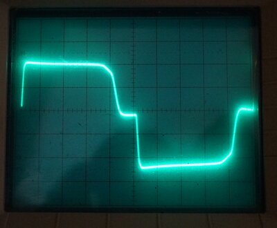
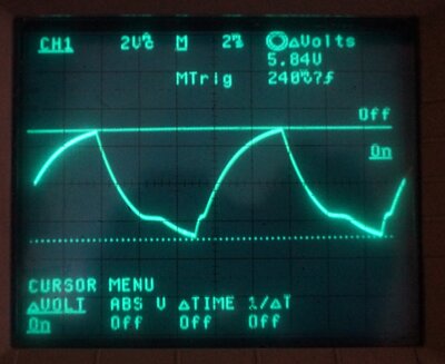
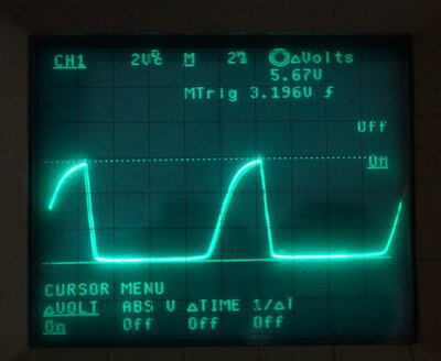
Output waveform at 15W and 75W loads respectively. Note the duty
cycle increases under load to maintain the rms voltage.
Regulation.
Input voltage at the 10,000uF was adjusted
in 500mV increments from 10 to 14V. A 40W load was used. Output voltage
was measured to observe regulation vs. supply voltage.
| Input voltage | Output voltage (40W load) |
| 10 | 207 |
| 10.5 | 214 |
| 11 | 220 |
| 11.5 | 225 |
| 12 | 231 |
| 12.5 | 236 |
| 13 | 241 |
| 13.5 | 246 |
| 14 | 251 |
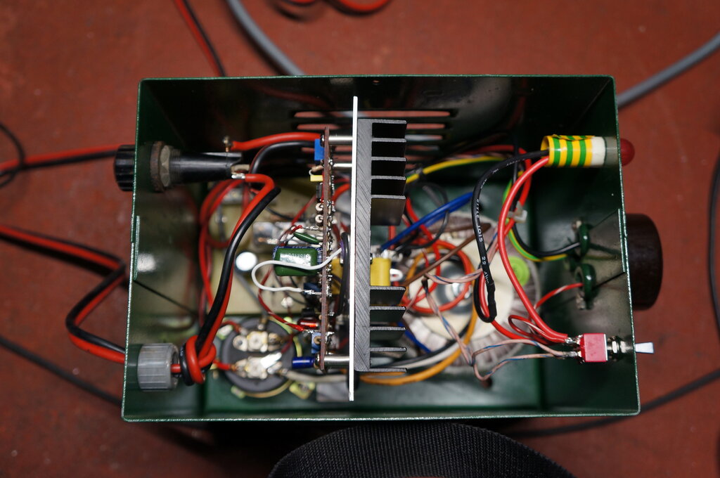
Internal view of assembled inverter.
It is quite remarkable to compare the inverter at the start of this project and what it ended up as. The 80VA transformer which was at first so difficult to use and inappropriate, turned out to work very well in the end by using some rather unconventional circuitry. The biggest surprise was the overall efficiency achieved.